Adjustable multifunctional excitation device of vibratory roller

A technology of vibratory road rollers and excitation devices, applied in roads, roads, road repairs, etc., can solve problems such as a single vibration mode, and achieve the effect of less rolling times, reasonable design, and good compaction effect

Active Publication Date: 2011-04-20
CHANGAN UNIV
View PDF0 Cites 0 Cited by
  • Summary
  • Abstract
  • Description
  • Claims
  • Application Information

AI Technical Summary

Problems solved by technology

[0008] The technical problem to be solved by the present invention is to overcome the defect of the single vibration mode of the vibrating wheel vibrating device of the above-mentioned vibratory roller, and provide an adjustable vibratory roller with reasonable design, simple structure, high efficiency, good compaction effect, and fewer rolling times. Functional vibration device

Method used


Image

  • Adjustable multifunctional excitation device of vibratory roller
  • Adjustable multifunctional excitation device of vibratory roller
  • Adjustable multifunctional excitation device of vibratory roller

Examples


Embodiment 1

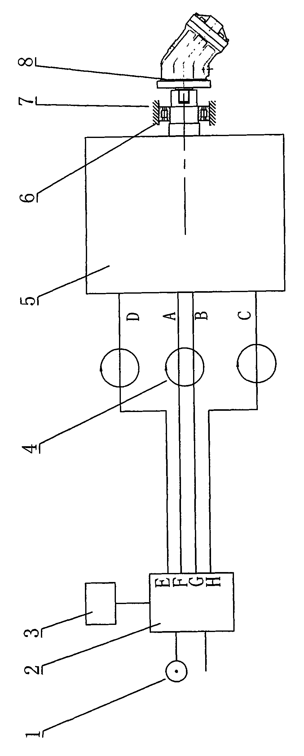
[0022] exist figure 1 Among them, the adjustable multifunctional vibration excitation device of the vibratory roller in this embodiment is connected by a hydraulic pump 1, a valve 2, a controller 3, a rotary joint 4, an exciter 5, a bearing 6, a vibration wheel 7 of the vibratory roller, and a hydraulic motor 8 constitute.

[0023] The exciter 5 is installed in the vibrating wheel 7 of the vibratory roller, and a bearing 6 is installed between the shaft of the vibrator 5 and the vibrating wheel 7 of the road roller, and a hydraulic motor 8 is fixedly connected to the end of the vibrator 5 with a coupling , the hydraulic motor 8 communicates with the hydraulic pump 1 of the vibratory roller through a pipeline, and the hydraulic motor 8 drives the vibrator 5 to rotate. The valve 2 communicates with the hydraulic pump 1 of the vibratory roller through a pipeline. The hydraulic pump 1 provides pressure oil. The valve 2 is an electromagnetic valve. The valve 2 is connected to the ...

Embodiment 2

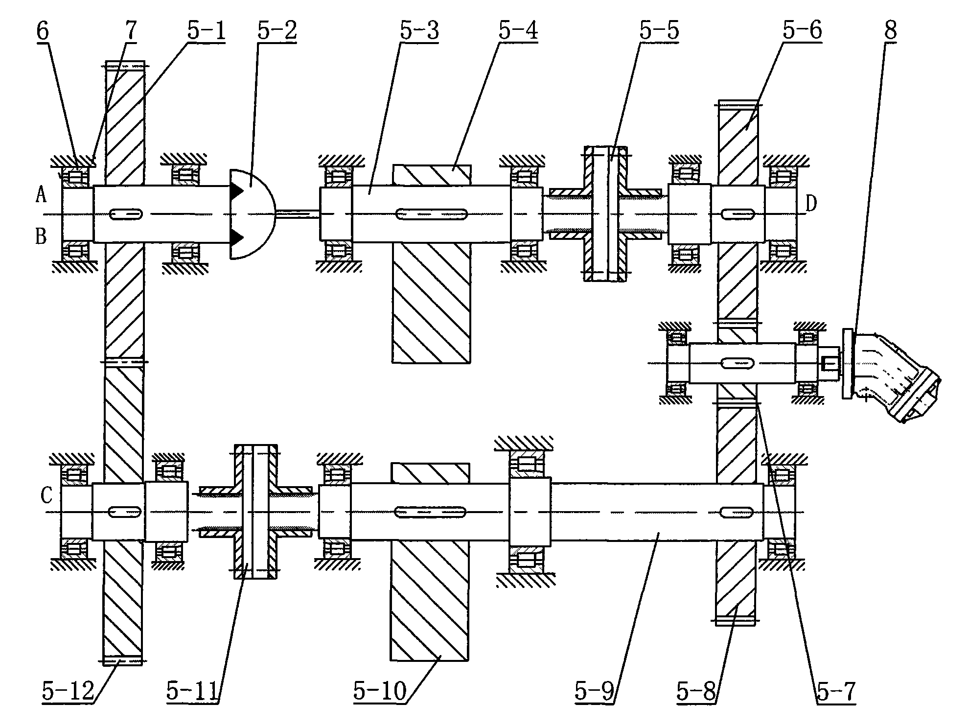
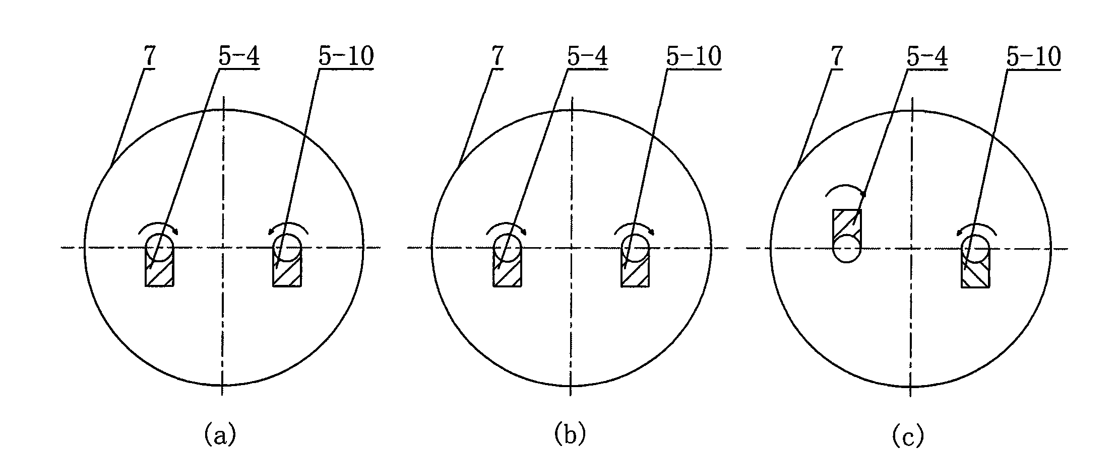
[0028] In this embodiment, the primary drive shaft 5-3 is splined with a primary clutch 5-5 and a primary eccentric block 5-4, and the primary clutch 5-5 is located between the primary eccentric block 5-4 and Between the first-stage forward gear 5-6, the distance between the installation axis of the first-stage eccentric block 5-4 and the center of gravity line is 5mm, and the mass of the first-stage eccentric block 5-4 is 200kg. The secondary drive shaft 5-9 is spline-connected with a secondary clutch 5-11 and a secondary eccentric block 5-10, and the secondary eccentric block 5-10 is located at the secondary forward gear 5-8 and the secondary clutch Between 5-11, the distance between the installation axis of the secondary eccentric block 5-10 and the center of gravity is 5mm, the mass of the secondary eccentric block 5-10 is 200kg, and the geometry of the secondary eccentric block 5-10 is the same as that of the primary The geometric shapes of the stage eccentric blocks 5-4 ...

Embodiment 3

[0030]In this embodiment, the primary drive shaft 5-3 is splined with a primary clutch 5-5 and a primary eccentric block 5-4, and the primary clutch 5-5 is located between the primary eccentric block 5-4 and Between the first-stage forward gears 5-6, the distance between the installation axis of the first-stage eccentric block 5-4 and the center of gravity line is 500 mm, and the mass of the first-stage eccentric block 5-4 is 0.5 kg. The secondary drive shaft 5-9 is spline-connected with a secondary clutch 5-11 and a secondary eccentric block 5-10, and the secondary eccentric block 5-10 is located at the secondary forward gear 5-8 and the secondary clutch Between 5-11, the distance between the installation axis of the secondary eccentric block 5-10 and the center of gravity is 500mm, the mass of the secondary eccentric block 5-10 is 0.5kg, and the geometric shape of the secondary eccentric block 5-10 is consistent with The geometric shapes of the first-level eccentric block 5-...


PUM


Abstract

The invention provides an adjustable multifunctional excitation device of a vibratory roller, which comprises a controller used for controlling the entire vibratory roller, wherein the controller is connected with a valve via conductors; the valve is communicated with a vibration exciter via a rotary connector and a hydraulic lock; the vibration exciter is characterized in that a main driving gear engaged with a primary forward gear and a secondary forward gear is arranged on the output shaft of a hydraulic motor; a primary driving shaft is arranged on the primary forward gear; a primary clutch and at least one primary eccentric block are arranged on the primary driving shaft; a gear shaft of a primary reverse gear is connected with a rotary oil cylinder; the oil port ends A and B of the rotary oil cylinder are communicated with the two corresponding oil port ends F and G of the valve via the rotary connector; the output shaft of the rotary oil cylinder is connected with the primary driving shaft; a secondary driving shaft is arranged on the secondary forward gear; a secondary clutch and at least one secondary eccentric block identical with the primary eccentric block are arrangedon the secondary driving shaft; and a secondary reverse gear engaged with the primary reverse gear is arranged at the other end of the secondary driving shaft.

Description

technical field [0001] The invention belongs to the technical field of paving and repairing machines, tools or auxiliary equipment for pavement of roads or other similar structures, and in particular relates to vibration compaction machinery in construction machinery. Background technique [0002] According to the compaction theory, the vibration modes of the vibration wheel excitation device include ordinary vibration compaction, vibration compaction, vertical vibration compaction and impact vibration compaction. [0003] Ordinary vibratory compaction relies on the combined action of the mass of the machine itself and the exciting force generated by the exciting device to reduce the internal friction between the particles of the pressed material, wedge the soil particles tightly, and achieve the purpose of compacting the soil. Vibratory compaction has the characteristics of concentrated static load and dynamic load combined compaction, and has the characteristics of strong ...

Claims


Application Information

Patent Timeline
Patent Type & Authority Patents(China)
IPC IPC(8): E01C19/28
Inventor 赵铁栓
Owner CHANGAN UNIV
Why Eureka
Try Eureka