Method and Apparatus for Catching and Retrieving Objects in a Well

a technology for catching and retrieving objects and wells, applied in the direction of fluid removal, borehole/well accessories, solid separation, etc., can solve the problems of destroying very expensive downhole equipment, affecting the operation of downhole equipment, and affecting the speed of falling objects, so as to slow down the velocity of falling objects passing through the bell nipple, improve the ability of the magnet assembly, and slow down the effect of falling objects

Inactive Publication Date: 2013-01-24
DEROUEN SR MARK W
View PDF5 Cites 7 Cited by
  • Summary
  • Abstract
  • Description
  • Claims
  • Application Information

AI Technical Summary

Benefits of technology

[0020]A diverter assembly can be mounted above the magnet assembly, and can act as a barrier to slow the velocity of a falling object passing through a bell nipple. Although said diverter assembly may only “break” the fall of an object, even a momentary reduction of velocity can greatly improve the ability of the magnet assembly to catch larger and/or heavier objects.
[0021]As a secondary function (in addition to slowing the velocity of falling objects), the diverter assembly of the present invention also acts as a wiper to clean the outer surface of pipe or other equ

Problems solved by technology

Unfortunately, not all objects that a bell nipple guides into a wellbore are beneficial.
If such objects are not stopped before entering the subterranean portion of the wellbore, the objects can prevent downhole equipment from functioning properly and can often impede the drilling and completion process.
By contrast, relatively small objects dropped in a wellbore and particularly metal objects—can often cause the most disruption to downhole equipment and related operations.
During open hole drilling operations, such small metal objects can destroy very expensive downhole equipment such as Polycrystalline Diamond Compact (PDC) bits.
Such small objects can also be very difficult to retrieve from a wellbore, as they are often too small to be grasped using conventional fishing tools.
Unfortunately, many drilling rigs typically have many small metal objects (such as, for example, wr

Method used


Image

  • Method and Apparatus for Catching and Retrieving Objects in a Well
  • Method and Apparatus for Catching and Retrieving Objects in a Well
  • Method and Apparatus for Catching and Retrieving Objects in a Well

Examples


Embodiment Construction

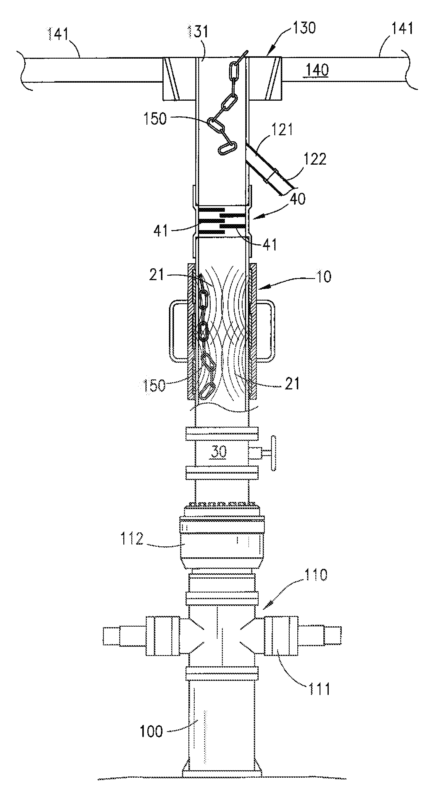
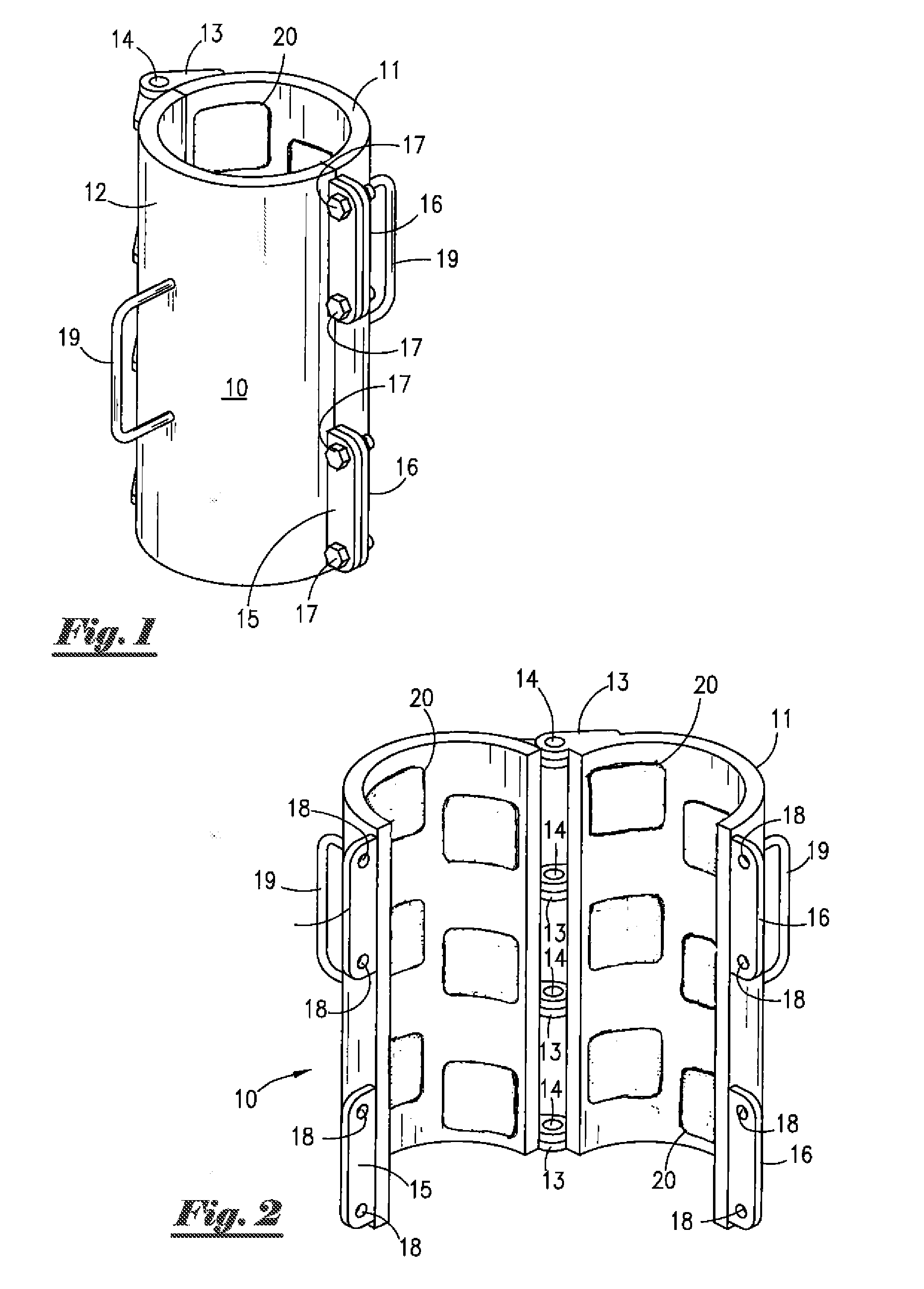
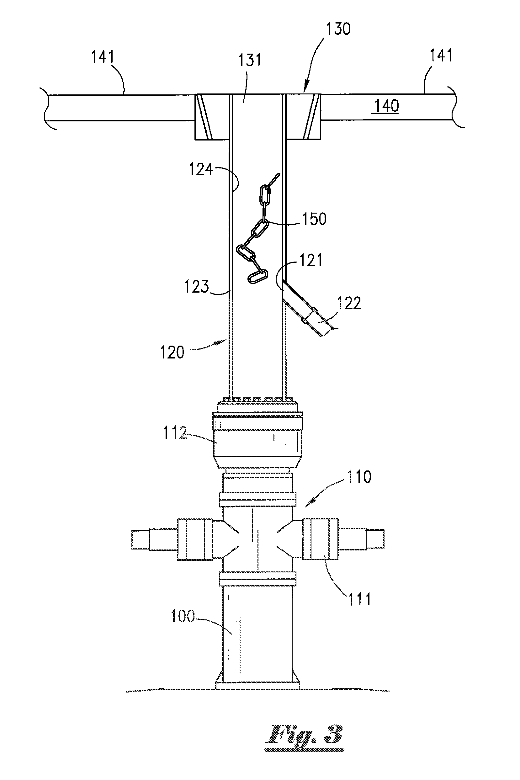
[0033]Referring to the drawings, FIG. 1 depicts a side perspective view of a magnet sleeve assembly 10 of the present invention in a closed position. Generally, said magnet sleeve assembly 10 of the present invention is installed in close proximity to the upper opening of a wellbore (such as, for example, near a bell nipple assembly). Said magnet sleeve assembly 10 generates a magnetic field that is beneficially directed toward the wellbore to catch falling metal objects and prevent such objects from entering the subterranean portions of said wellbore.

[0034]Still referring to FIG. 1, magnet sleeve assembly 10 comprises first semi-cylindrical member 11 and second semi-cylindrical member 12 joined by at least one hinge assembly comprising hinge body members 13 and hinge pin 14. When said first and second semi-cylindrical members are joined together as depicted in FIG. 1, magnet sleeve assembly 10 has a substantially cylindrical shape. In the preferred embodiment depicted in FIG. 1, ma...


PUM


Abstract

A magnet assembly can be attached to, or placed in the vicinity of, a conventional bell nipple to generate a magnetic field within the central bore of the bell nipple. The magnetic field catches falling metal objects and prevents such objects from passing beyond the bell nipple and entering the subterranean portions of a wellbore. An optional diverter assembly slows the velocity of falling metal objects before reaching the magnet assembly, while also wiping the outer surface of pipe or other items lowered into a wellbore.

Description

CROSS REFERENCES TO RELATED APPLICATION[0001]PRIORITY OF U.S. PROVISIONAL PATENT APPLICATION SER. NO. 61 / 510,229, FILED Jul. 21, 2011, AND U.S. PROVISIONAL PATENT APPLICATION SER. NO. 61 / 610,757, FILED Mar. 14, 2012, BOTH INCORPORATED HEREIN BY REFERENCE, IS HEREBY CLAIMED.STATEMENTS AS TO THE RIGHTS TO THE INVENTION MADE UNDER FEDERALLY SPONSORED RESEARCH AND DEVELOPMENT[0002]NONEBACKGROUND OF THE INVENTION[0003]1. Field of the Invention[0004]The present invention pertains to a method and apparatus for preventing unwanted objects from entering subterranean portions of a wellbore. More particularly, the present invention pertains to the use of magnetic field(s) to catch falling objects within a wellbore. More particularly still, the present invention pertains to an apparatus for generating magnetic field(s) between a rig floor of a drilling or completion rig and a wellhead, such as in or near a bell nipple assembly, in order to prevent unwanted objects from falling into a wellbore b...

Claims


Application Information

Patent Timeline
IPC IPC(8): E21B31/06E21B23/00
CPCE21B41/0021E21B31/06B03C1/0332B03C1/26B03C1/288B03C2201/20B03C2201/28E21B33/068
Inventor DEROUEN, SR., MARK W.
Owner DEROUEN SR MARK W
Why Eureka
Try Eureka