Data Transport System and Control Method of Data Transport System

Inactive Publication Date: 2013-01-24
HITACHI LTD
View PDF10 Cites 11 Cited by
  • Summary
  • Abstract
  • Description
  • Claims
  • Application Information

AI Technical Summary

Benefits of technology

[0019]According to an exemplary embodiment of this invention, the path calculation load on communication dev

Problems solved by technology

This means that a large-scale router communication network using a transport network cannot be built with the conventional method.
However, the exchange of

Method used


Image

  • Data Transport System and Control Method of Data Transport System
  • Data Transport System and Control Method of Data Transport System
  • Data Transport System and Control Method of Data Transport System

Examples


Example

First Embodiment

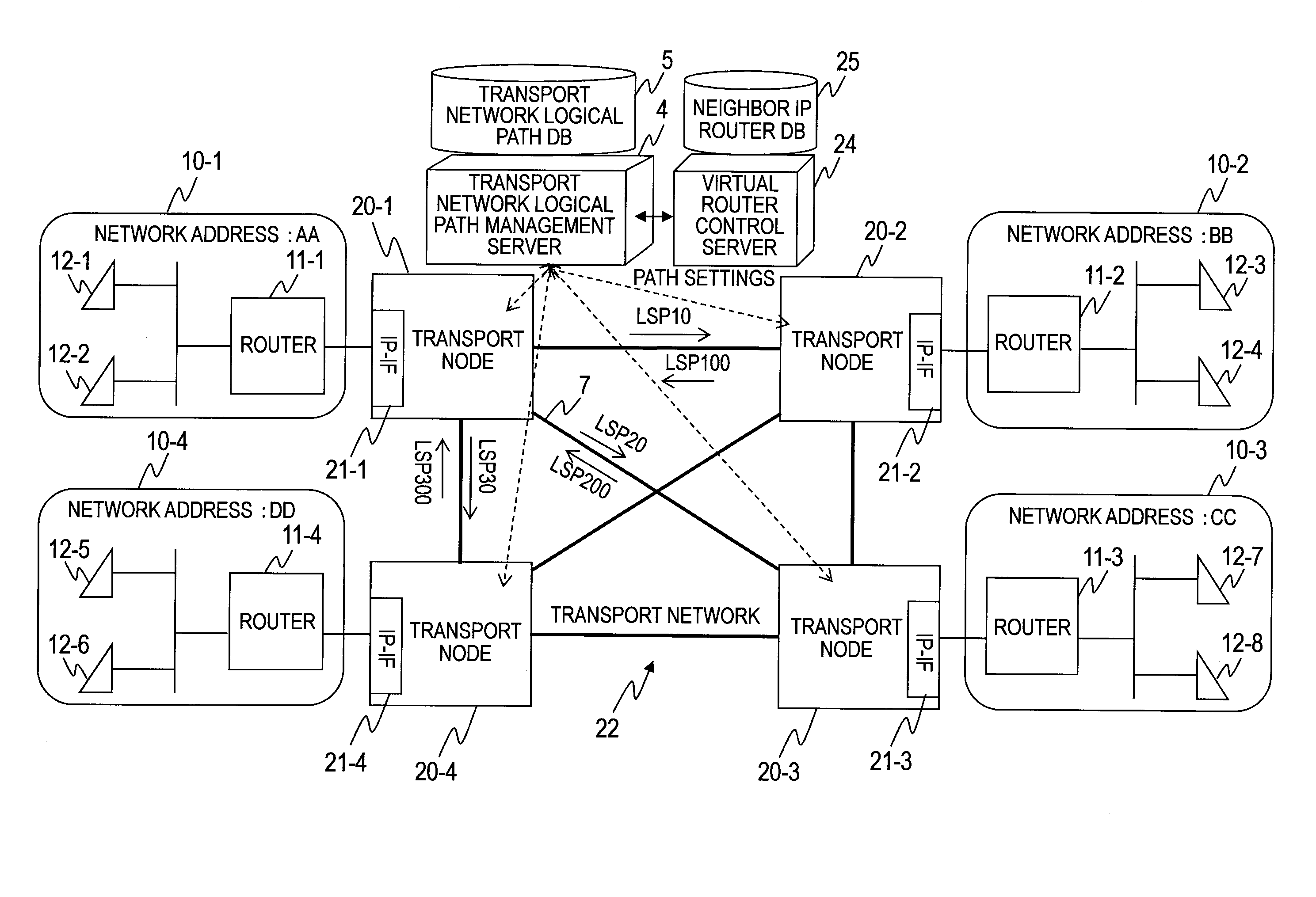
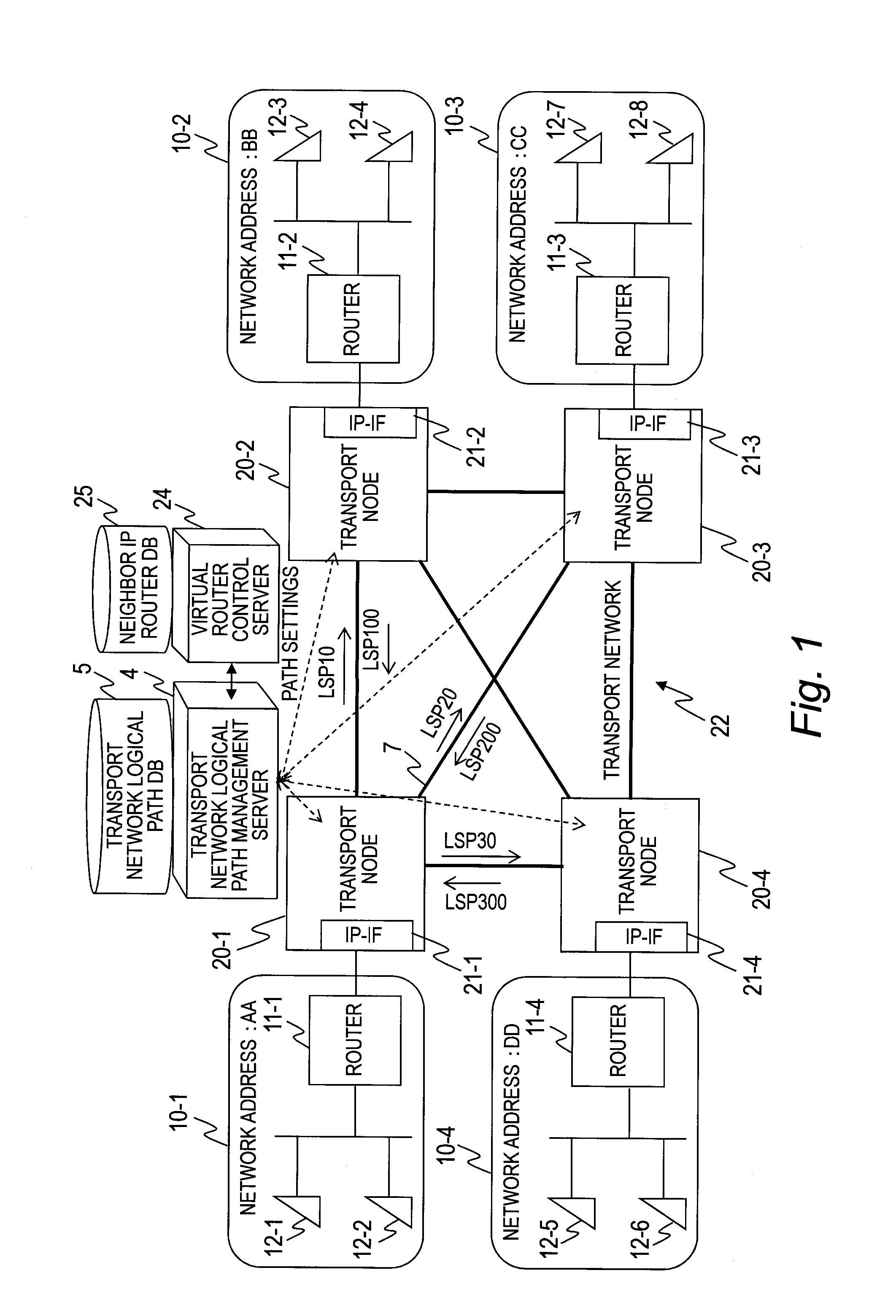
[0046]FIG. 1 is a diagram illustrating an example in which routers owned by a transport network user are connected to a data transport system according to a first embodiment of this invention.

[0047]In the data transport system of FIG. 1, a telecommunication carrier provides a transport network 22 and the transport network user rents logical paths 7 of the transport network 22 from the telecommunication carrier. Four sites of the transport network user which are geographically distant from one another and which are denoted by 10-1 to 10-4 (bases 10-1 to 10-n, n is 4 in FIG. 1) are connected to one another via the transport network 22 of the telecommunication carrier.

[0048]The bases 10-1 to 10-n of the transport network user include routers (communication devices) 11 (11-1 to 11-n), which connect to the transport nodes 20 (20-1 to 20-n), and include communication terminals 12 (12-1 to 12-m). The communication terminals 12-1 to 12-m are, for example, routers, personal c...

Example

[0185]A second embodiment of this invention is described below with reference to the drawings. The difference in configuration of the second embodiment from the first embodiment is what contents are held in an entry of the routing information table 45 of the IP-IF card 21 which is provided in each of the transport nodes 20-1 to 20-n.

[0186]Settings of logical paths in the transport network 22 according to the second embodiment are described first with reference to FIGS. 1 and 16.

[0187]Logical paths set in the transport network 22 to and from the transport node 20-1 are the transmission LSP 10 and the reception LSP 100, which are formed with the transport node 20-2, the transmission LSP 20 and the reception LSP 200, which are formed with the transport node 20-3, and the transmission LSP 30 and the reception LSP 300, which are formed with the transport node 20-4.

[0188]FIG. 16 is a diagram illustrating an example of the contents of an entry in the routing information table 45 of the tr...

Example

Third Embodiment

[0208]A third embodiment of this invention is described below with reference to the drawings. The difference in configuration of the third embodiment from the first embodiment is that routers have IP-IF cards and that the IP-IF cards of the routers are included as subjects of monitoring by a transport network logical path management server and a virtual router control server.

[0209]A connection configuration of the data transport system and a configuration of routers according to the third embodiment are described with reference to FIGS. 18 and 19.

[0210]FIG. 18 is a diagram illustrating physical connections of the data transport system according to the third embodiment. In the data transport system according to the third embodiment, a telecommunication carrier provides a transport network 122 and a transport network user rents logical paths 7 of the transport network 122 from the telecommunication carrier. Four sites which are geographically distant from one another a...


PUM


Abstract

An example of a data transport system includes transport nodes of a transport network, communication devices which communicate via the transport network, and a transport network logical path management server for setting logical paths between the transport nodes within the transport network, and a logical path control server. In a case where a first communication device is newly connected with a first transport node, the first communication device transmits control data to a logical path control server via the first transport node. The logical path control server obtains information about a connection relation between the newly connected first communication device and the first transport node from the control data, and establishes a logical path between the first communication device and a second communication device based on the obtained information about the connection relation and on information about logical paths between transport nodes in a logical path database.

Description

CLAIM OF PRIORITY[0001]The present application claims priority from Japanese patent application JP 2011-159863 filed on Jul. 21, 2011, the content of which is hereby incorporated by reference into this application.BACKGROUND OF THE INVENTION[0002]This invention relates to a technology for establishing a logical path between communication devices.[0003]Telecommunication carriers that use a connection-oriented communication protocol to build a transport network are known. Examples of communication protocols for building a transport network include Multiprotocol Label Switching-Transport Profile (MPLS-TP), Provider Backbone Bridges (PBB), and Asynchronous Transfer Mode (ATM). With these communication protocols, an end-to-end logical path can be built to provide a highly confidential logical path. These communication protocols also have an Operation, Administration and Maintenance (OAM) function for monitoring the logical path for the presence or absence of a failure, and an Automatic P...

Claims


Application Information

Patent Timeline
IPC IPC(8): H04L12/56H04L45/28H04L45/02H04L45/24H04L45/42H04L45/50
CPCH04L45/02H04L45/28H04L45/22H04L45/247H04L45/03
Inventor TAKASE, MASAYUKIKIMURA, MASAHIROKUSAMA, KAZUHIRO
Owner HITACHI LTD
Why Eureka
Try Eureka