
Methods of coating wellbore tools and components having such coatings

Active Publication Date: 2013-01-31
BAKER HUGHES INC
View PDF1 Cites 12 Cited by
  • Summary
  • Abstract
  • Description
  • Claims
  • Application Information

AI Technical Summary

Benefits of technology

This patent describes a method and device for coating a wellbore tool with a pattern of features and a protective coat. The coat can be applied without using adhesive between the tool and the coat. The technical effects of this patent include improved abrasion resistance, corrosion resistance, and improved durability of the wellbore tool.

Problems solved by technology

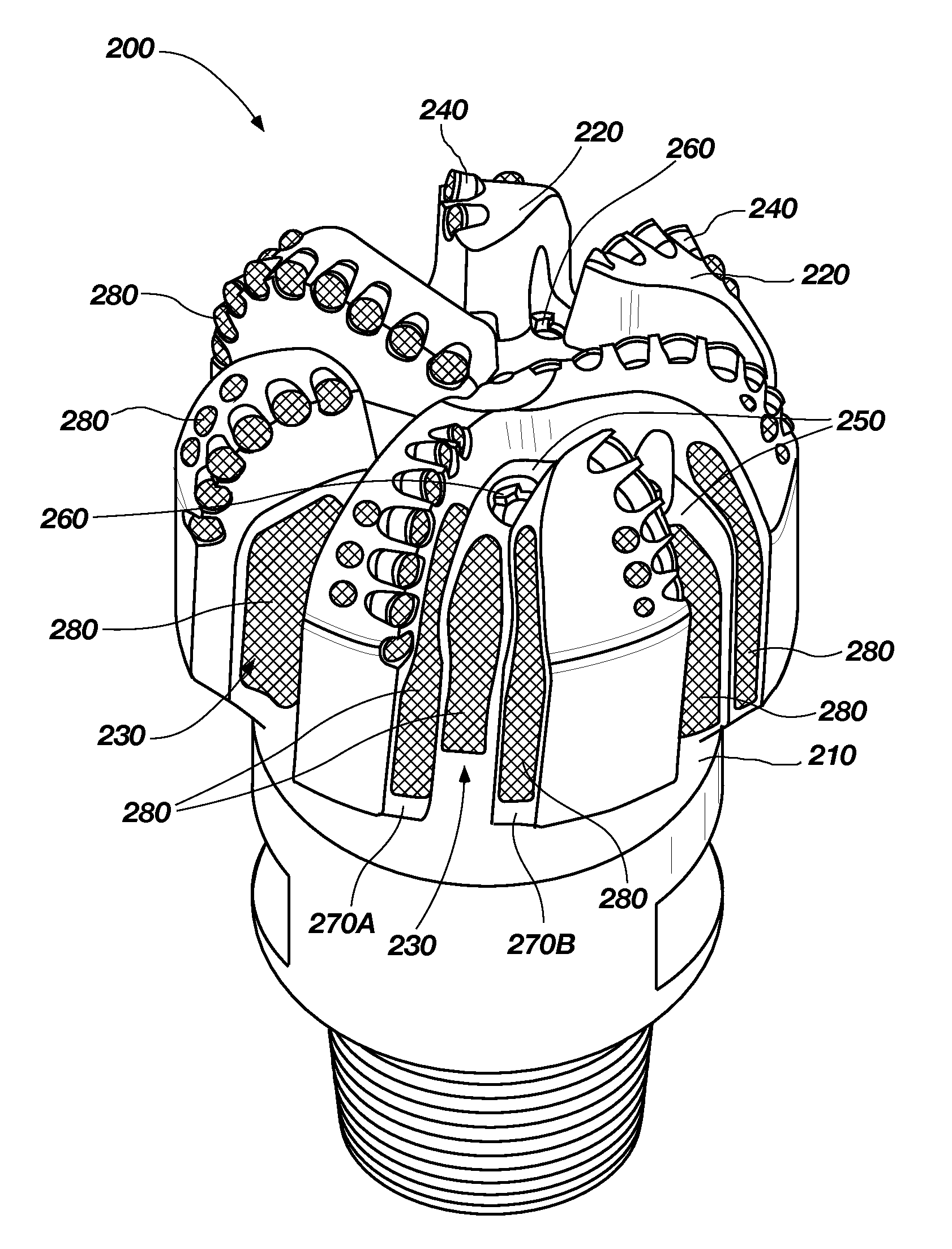
Drilling tools used for casing and liner drilling usually have smaller fluid courses and are particularly prone to balling, which results in a lower rate of penetration.
Moreover, particles of the formation may be compacted onto surfaces of the tool or mechanically bonded into pits or trenches etched into the tool by erosion and abrasion during the drilling process.
In some cases, drilling operations are conducted with reduced or mitigated hydraulics, which tend to result in the aforementioned balling problems.
For example, some drilling rigs may not have pumps with sufficient capacity to provide desirable pressures and flow rates of drilling fluid for drilling to the depths required.
Furthermore, operators sometimes find it too costly to run higher mud flow rates or find that high flow rates cause unacceptable wear and erosion of the BHA.
Because of the prolonged contact of wellbore tools with pressurized fluids and debris, in addition to the generally-harsh conditions of a downhole location, when drilling, completing, testing, stimulating, producing or remediating a wellbore, surfaces of drill bits, drill strings, tool string, and components thereof become damaged due to erosion, abrasion, and / or corrosion.
Damage may occur on interior and / or exterior surfaces of such components.
Such damage may lead to corrosion and premature failure of such components and to additional costs associated with removal and repair or replacement of damaged components.

Method used


Image

  • Methods of coating wellbore tools and components having such coatings
  • Methods of coating wellbore tools and components having such coatings
  • Methods of coating wellbore tools and components having such coatings

Examples


embodiment 1

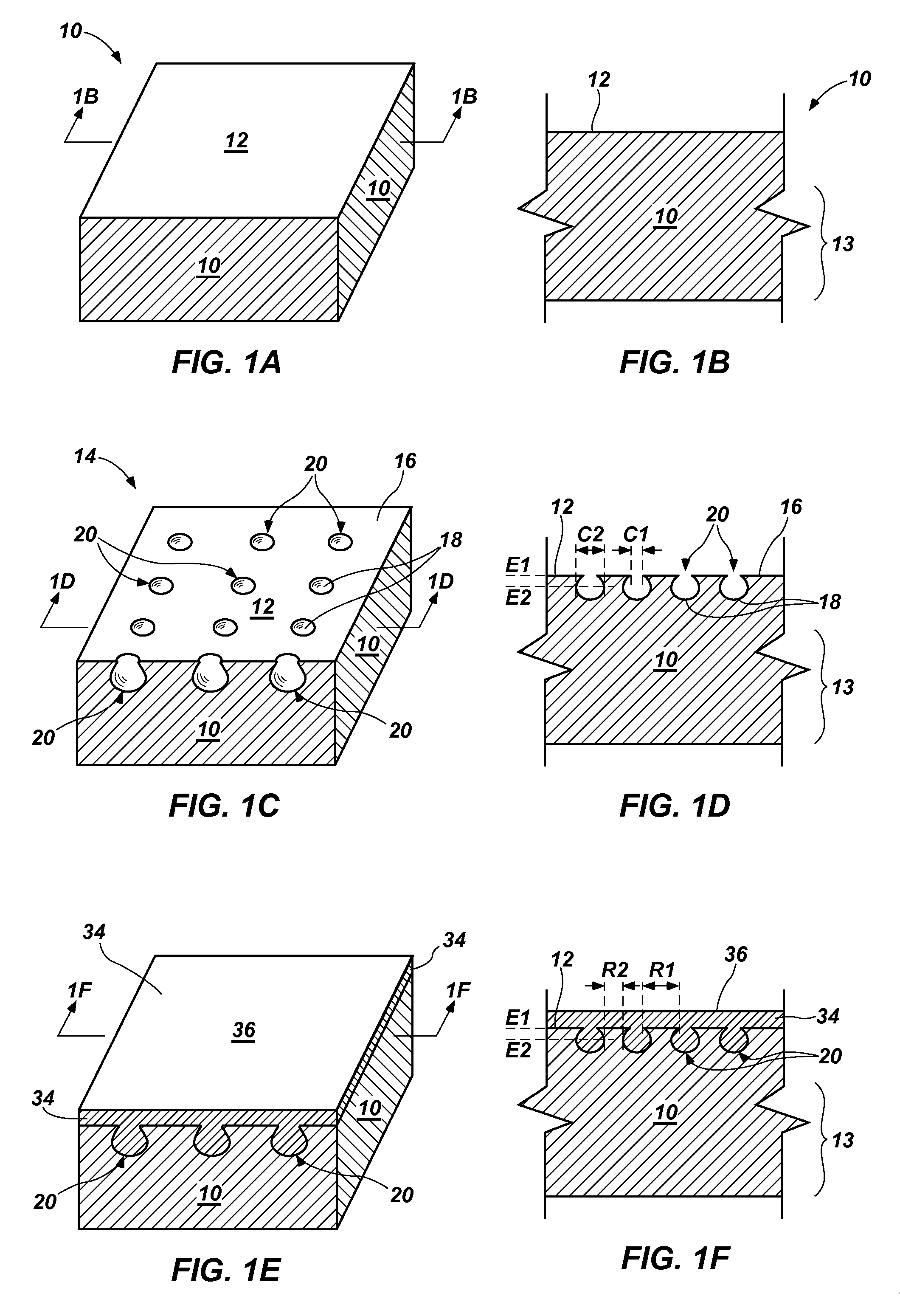
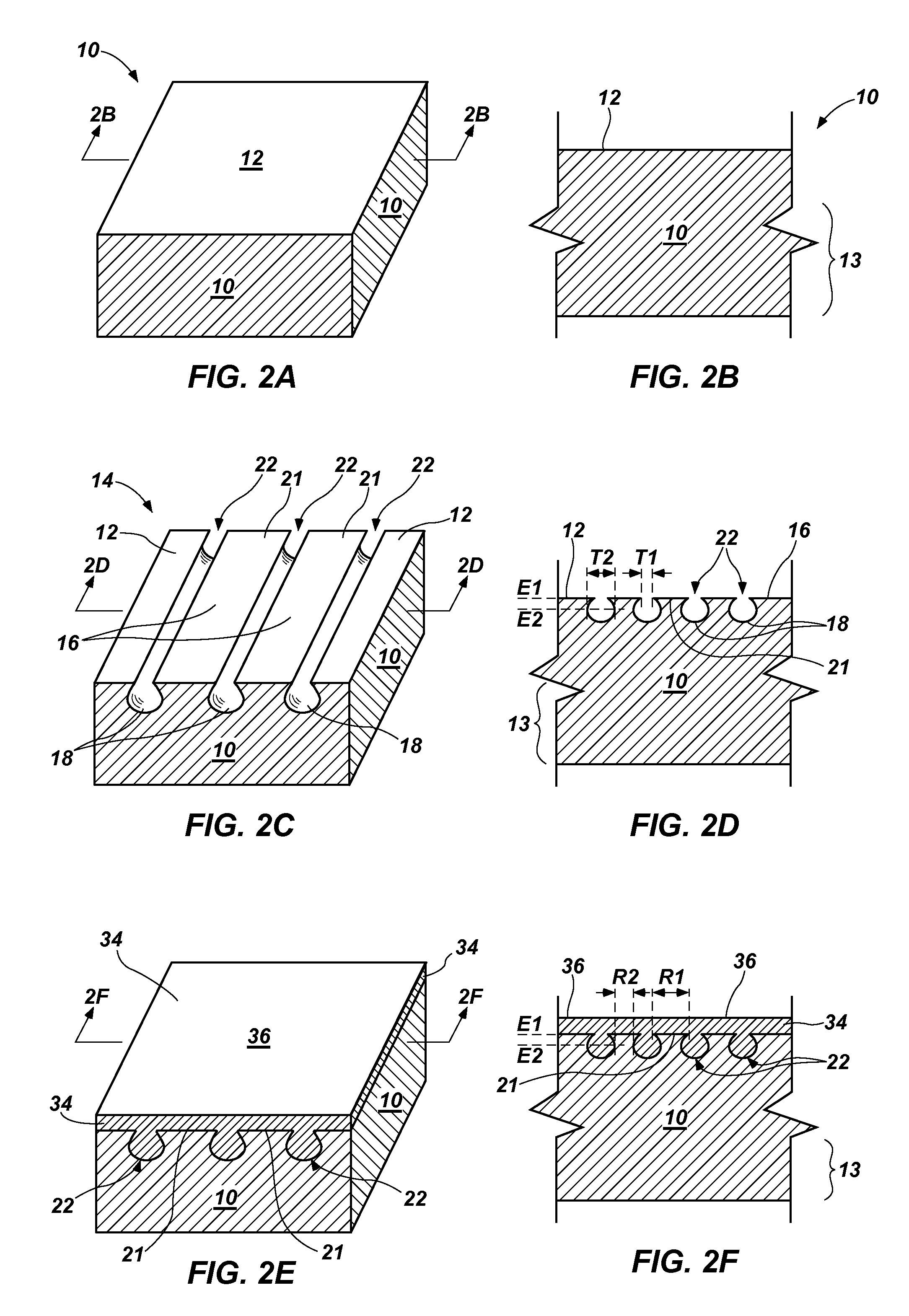
[0116]A method for forming a coating upon a wellbore tool, comprising forming a body comprising an outer surface and an interior region; forming a pattern of features supported by the body, comprising: forming a first feature; and forming a second feature spaced from the first feature by a first width at a first elevation and by a second width at a second elevation, the second width being different than the first width, the first elevation being further from the interior region than the second elevation; and forming a coating over the pattern of features.

embodiment 2

[0117]The method of Embodiment 1, wherein forming the first feature comprises forming a first cavity; and forming the second feature spaced from the first feature comprises forming a second cavity spaced from the first cavity.

embodiment 3

[0118]The method of Embodiment 2, wherein forming the first cavity and forming the second cavity comprise selectively exposing the outer surface of the body to laser irradiation to remove material therefrom.


PUM

PropertyMeasurementUnit
Widthaaaaaaaaaa

Abstract

A method for forming a coating upon a wellbore tool includes forming a pattern of features supported by a body and forming a coating over the pattern of features. Forming the pattern of features includes forming a first feature and forming a second feature spaced from the first feature by a first width at a first elevation and by a second width at a second elevation, the second width being different than the first width, and the first elevation being further from an interior region of the body than the second elevation. Also disclosed is a wellbore tool comprising a coating covering a pattern of features and a method of utilizing a wellbore tool in a subterranean formation, the method including forming a pattern of features, forming a coating over the pattern, and disposing the wellbore tool in a borehole.

Description

FIELD[0001]Embodiments of the present disclosure relate to methods used to provide a coating on a wellbore tool and to wellbore tools including such coatings.BACKGROUND[0002]Wellbores are formed in subterranean formations for various purposes including, for example, extraction of oil and gas from the subterranean formation and extraction of geothermal heat from the subterranean formation. Wellbores may be formed in a subterranean formation using a drill bit such as, for example, an earth-boring rotary drill bit. Different types of earth-boring rotary drill bits are known in the art including, for example, fixed-cutter bits (which are often referred to in the art as “drag” bits), rolling-cutter bits (which are often referred to in the art as “rock” bits), diamond-impregnated bits, and hybrid bits (which may include, for example, both fixed cutters and rolling cutters). The drill bit is rotated and advanced into the subterranean formation. As the drill bit rotates, the cutters or abra...

Claims


Application Information

Patent Timeline
IPC IPC(8): E21B7/00E21B10/36B05D3/10C23F1/02B05D3/12B05D3/00
CPCC23C30/005E21B49/10E21B4/02F04C13/008F04C2/1071F03C2/08F04C2230/91E21B10/46
Inventor KUMAR, SUNILJOHN, HENDRIK
Owner BAKER HUGHES INC
Learn More