Speed Change Control System for a Vehicle

a control system and vehicle technology, applied in brake systems, process and machine control, instruments, etc., can solve the problems of difficult to set the constant speed mode to the same speed as before, and the speed change control system is difficult to achiev

Active Publication Date: 2013-01-31
KUBOTA LTD
View PDF5 Cites 20 Cited by
  • Summary
  • Abstract
  • Description
  • Claims
  • Application Information

AI Technical Summary

Benefits of technology

[0072]Other features and their advantageous effects will be apparent upon reading the detail description as under with reference to the drawings.

Problems solved by technology

However, with the constant speed mode control using a constant speed lever which is retained by means of friction, the friction makes accurate setting of a constant vehicle travel speed difficult.
Especially, after release of the constant speed mode by lowering the constant speed lever to the zero speed position, it is difficult to set the constant speed mode to the same speed as before.

Method used


Image

  • Speed Change Control System for a Vehicle
  • Speed Change Control System for a Vehicle
  • Speed Change Control System for a Vehicle

Examples


Embodiment Construction

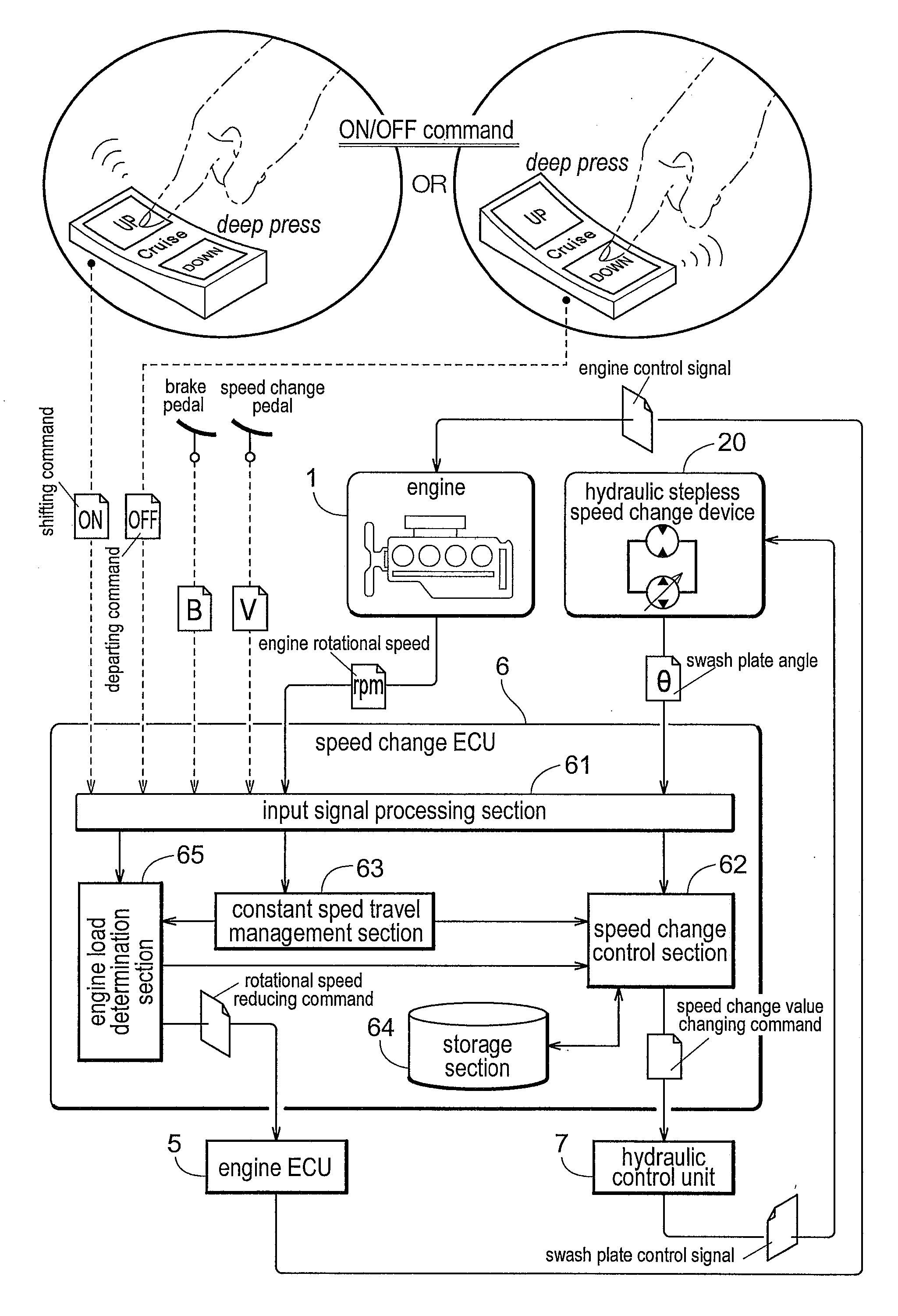
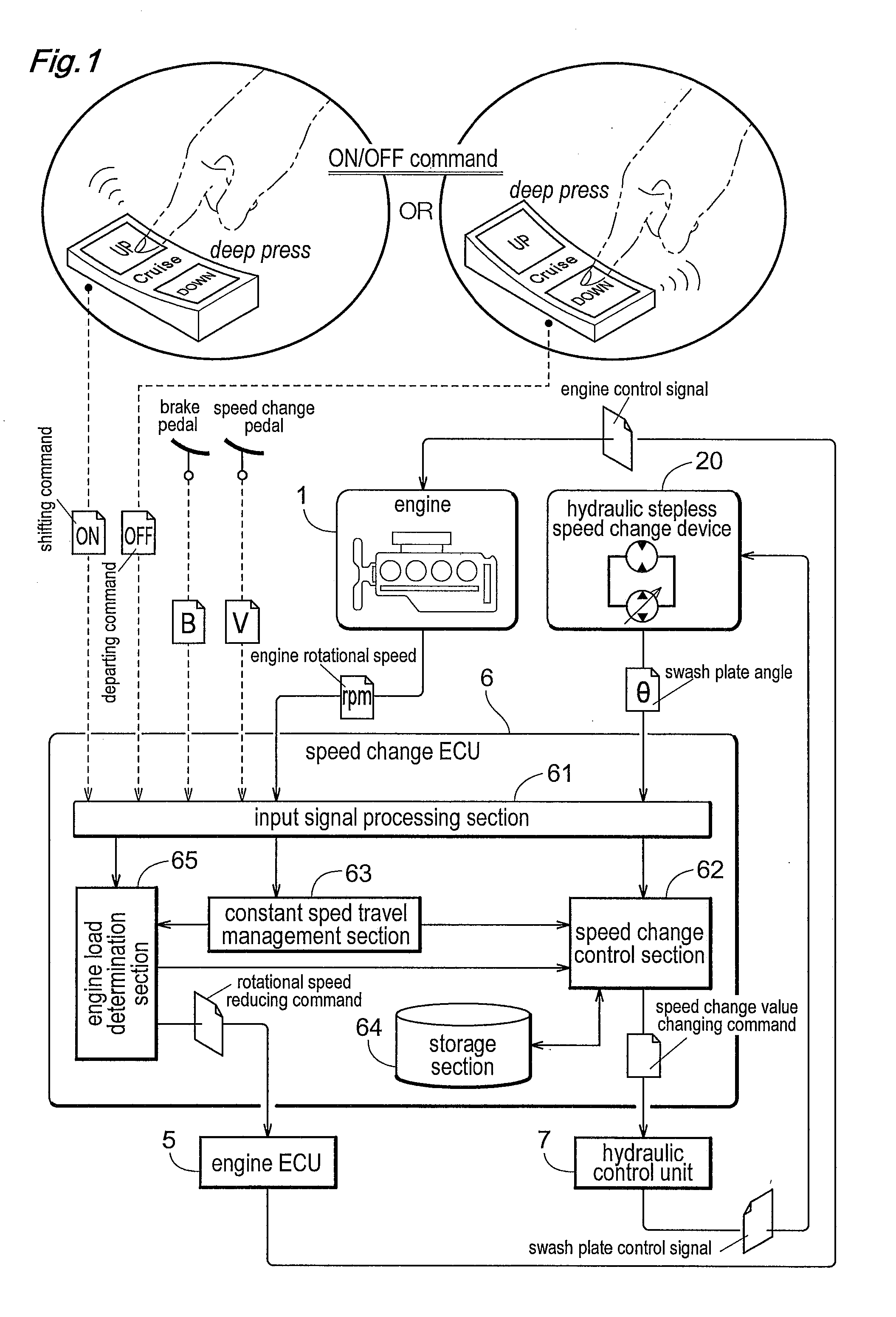
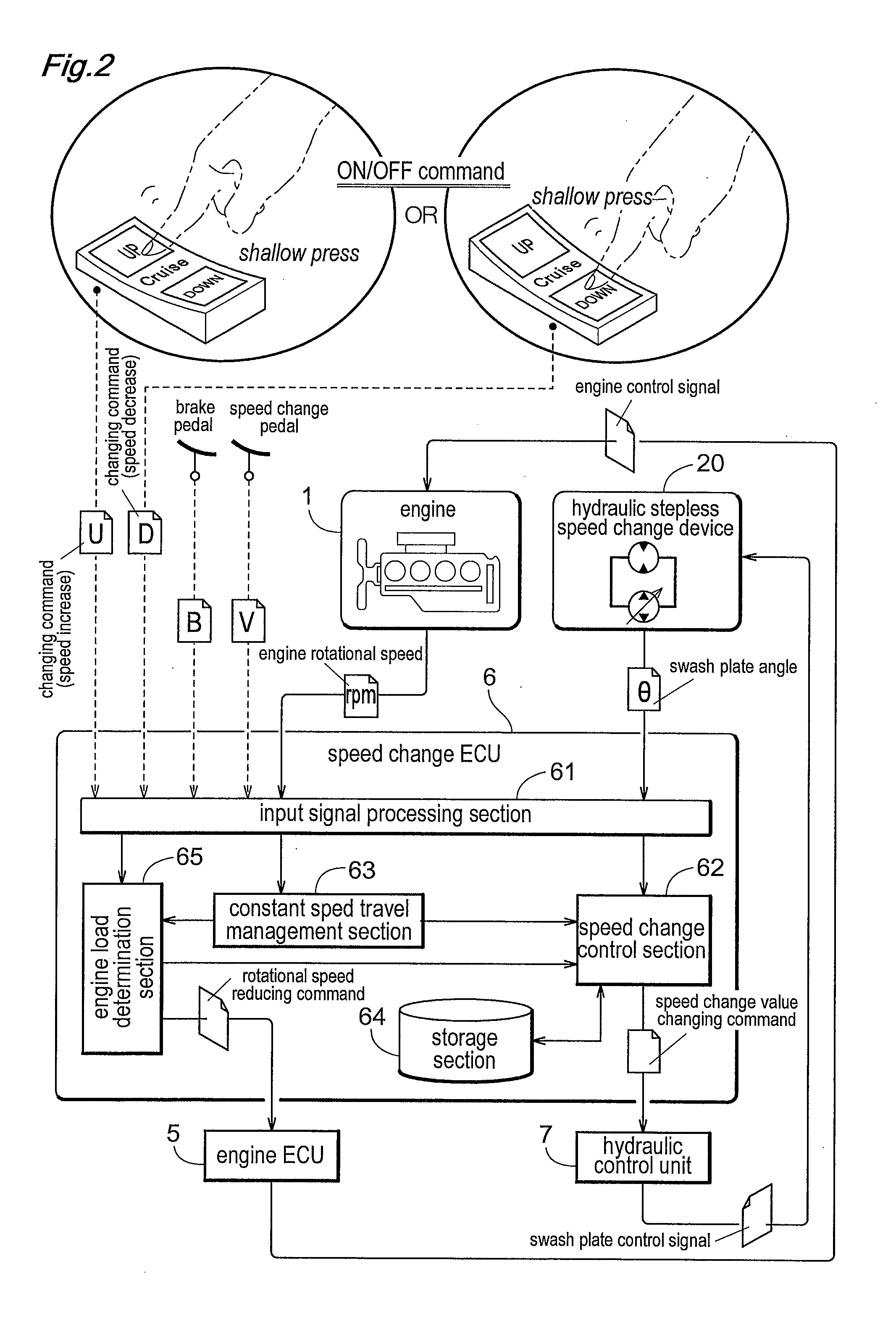
[0088]Before giving specific description of embodiments of the present invention, description will be given with reference to FIG. 1 and FIG. 2 on the basic principle of a constant speed mode control for realizing a constant speed vehicle travel by the inventive speed change control system. FIG. 1 is a schematic diagram illustrating a control flow of shifting to a constant speed mode and of departing from the constant speed mode. FIG. 2 is a schematic diagram illustrating a control flow of speed increase / decrease of the vehicle speed at the time of the constant speed mode. Here, as a stepless speed change device, a hydraulic stepless speed change device 20, such as a hydrostatic stepless speed change device (HST) or a hydraulic mechanical stepless speed change device (HMT), is employed. And, a speed change operational tool is constituted of a speed change pedal.

[0089]A constant speed travel operational device is constituted of a seesaw type switch 90 (“constant speed switch” hereina...


PUM


Abstract

A speed change control system includes a speed change control section for setting a speed change value of a stepless speed change device; a speed change operational tool for providing the speed change control section with a speed change command the stepless speed change device; a constant speed travel operational device for providing the speed change control section with a changing command for changing a constant speed mode speed change value which is a speed change value at the time of the constant speed mode, a shifting command for shifting to the constant speed mode and a departing command for departing from the constant speed mode; and a constant speed travel management section which causes the speed change control section to execute the constant speed mode with the constant speed mode speed change value, based on the shifting command from the constant speed travel operational device.

Description

BACKGROUND OF THE INVENTION[0001]1. Field of the Invention[0002]The present invention relates to a speed change control system having a constant speed mode for causing a vehicle to travel at a constant speed, which vehicle includes a stepless speed change device for steplessly speed-changing a rotational power from an engine and outputting the speed-changed power.[0003]2. Description of the Related Art[0004]The constant speed mode for causing a vehicle to travel at a constant speed is called also a cruising mode. This mode is used when a work vehicle such as a tractor carries out a utility work such as a cultivating work, a ground leveling work, etc., while the vehicle travels at a constant speed. With using this constant speed mode, the driver or operator is free from the trouble of vehicle speed adjustment. A work vehicle having such constant speed mode is disclosed in Japanese unexamined patent application publication No. 2008-037400 (JP 2008-037400 A) (paragraphs through [00087]...

Claims


Application Information

Patent Timeline
Patent Type & Authority Applications(United States)
IPC IPC(8): B60K31/00
CPCF16H61/46B60W10/06B60W10/103B60K31/00B60W30/1888B60K2310/20B60W2300/156B60W30/143B60K20/00F16H61/02
Inventor FUJIMOTO, HIROOTANIMURA, ISSEIKUROSHITA, YOSHIHIKO
Owner KUBOTA LTD
Why Eureka
Try Eureka