
Device for calculating impedances of battery cell and battery impedance measuring system

a technology of impedance measurement and battery cell, which is applied in the direction of measurement devices, resistance/reactance/impedence, instruments, etc., can solve the problems of insufficient output voltage, inability to produce sufficient output, and difficulty in mounting the measuring circui

Active Publication Date: 2013-01-31
YOKOGAWA ELECTRIC CORP
View PDF2 Cites 17 Cited by
  • Summary
  • Abstract
  • Description
  • Claims
  • Application Information

AI Technical Summary

Benefits of technology

The present invention provides a battery impedance measuring device that can measure the internal impedance of a battery in real-time on the spot, such as in a vehicle, power plant, or household power storage system. The device includes a Fourier transformation calculator, a circuit model selector, and an impedance estimator that can calculate the impedance of the battery cell for different frequencies. The device can also store the non-variable and variable circuit constants of the battery cell for future reference. The technical effect of the invention is to provide a device that can accurately measure the impedance of a battery in real-time, which can help to improve the performance and monitoring of battery-based systems.

Problems solved by technology

As the impedance increases, voltage drop of a battery increases when producing a current, and thus a sufficient output voltage may not be obtained.
That is, an output characteristic varies according to deterioration of the battery, and thus a sufficient output may not be produced.
In addition, according to the measuring circuit in the related art as shown in FIG. 13, the sweep signal generator 50 is necessary, and it is difficult to mount the measuring circuit as shown in FIG. 13 in each of the on-site cells in terms of both cost and space.

Method used


Image

  • Device for calculating impedances of battery cell and battery impedance measuring system
  • Device for calculating impedances of battery cell and battery impedance measuring system
  • Device for calculating impedances of battery cell and battery impedance measuring system

Examples


Embodiment Construction

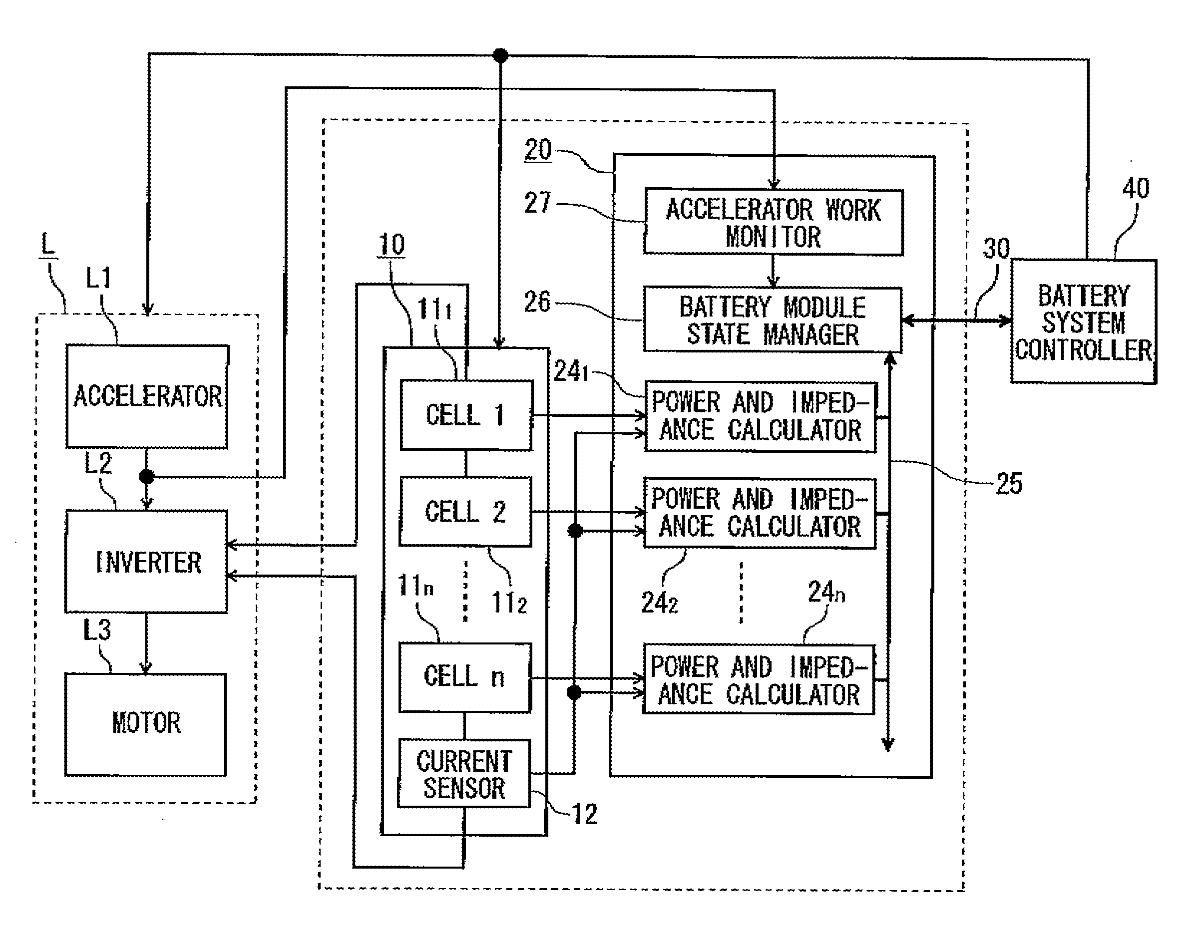
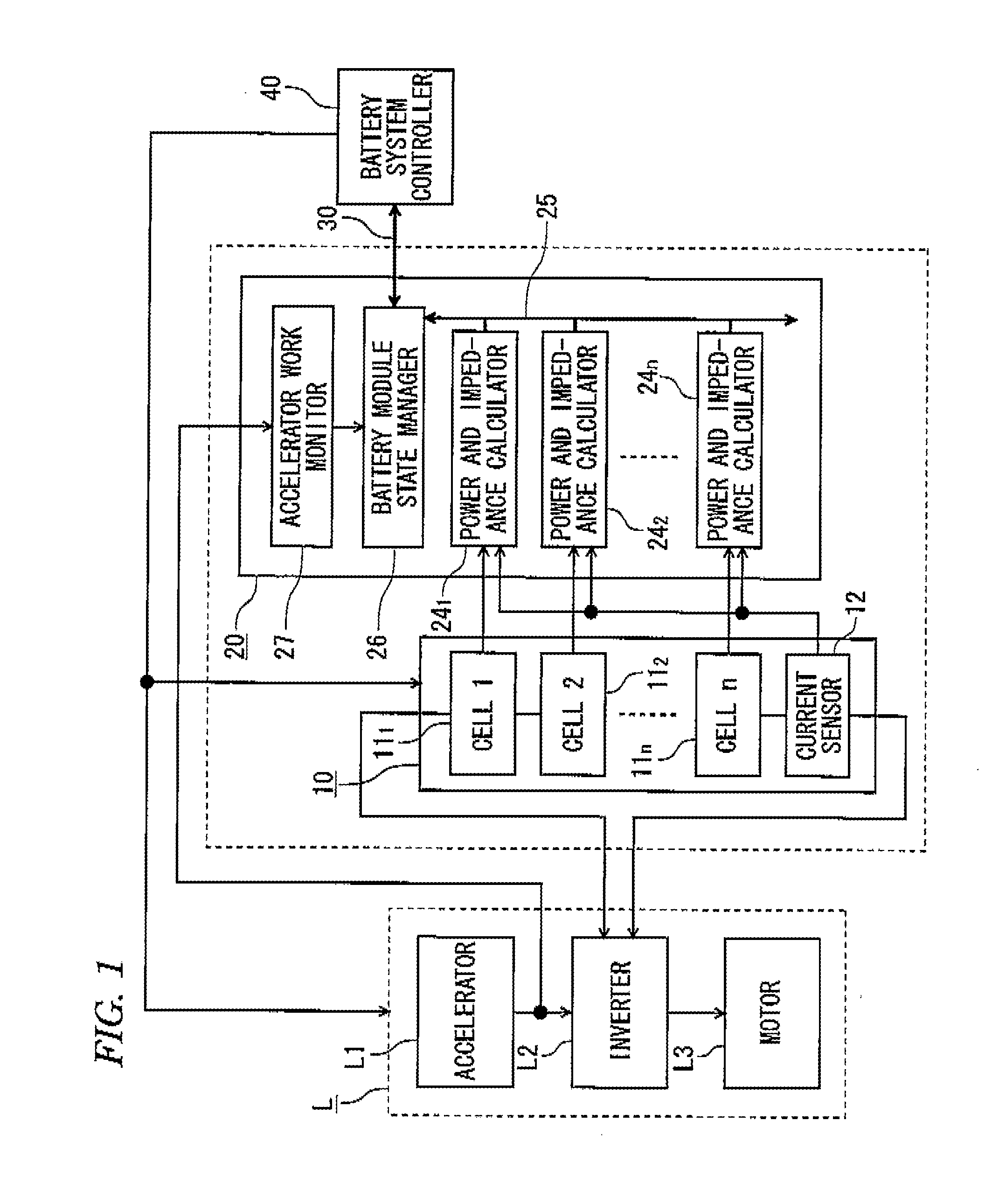
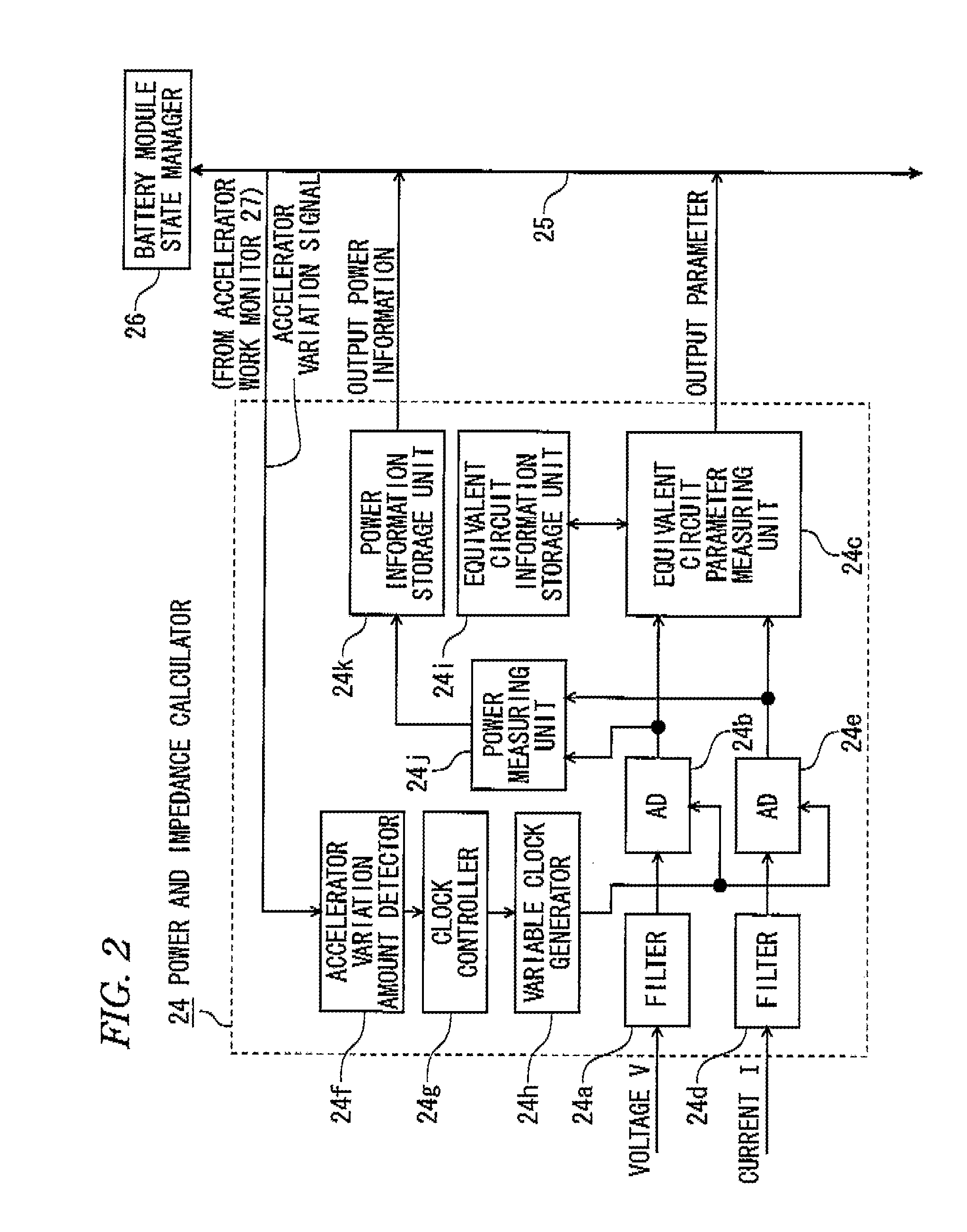
[0049]Hereinafter, embodiments of the invention will be described in detail with reference to the attached drawing. FIG. 1 is a block diagram illustrating a specific example of a battery monitoring device in which a battery impedance measuring device according to the invention is used, and the same reference numerals are attached to the same portions as FIG. 10. In FIG. 1, a battery monitoring device 20 includes a plurality of n power and impedance calculators 241 to 24n that are provided in correspondence with a plurality of n battery cells 111 to 11n that make up a battery module 10, a battery module state manager 26 to which output data of the power and impedance calculators 241 to 24n is input via an internal bus 25, and an accelerator work monitor 27 that monitors movement of an accelerator L1 makes up a driving system of a vehicle as a load device L.

[0050]In the driving system of a vehicle as the load device L, the accelerator L1, an inverter L2, and a motor L3 are substantial...


PUM


Abstract

There is provided a device for calculating impedances of a battery cell for respective frequency domains. The device includes: a Fourier transformation calculator configured to perform Fourier transformation on voltage waveform data and current waveform data, which are output from the battery cell, and calculate an impedance of the battery cell by dividing a Fourier transformation data of the voltage waveform data by a Fourier transformation data of the current waveform data; a circuit constant estimator configured to estimate circuit constants of a predetermined equivalent circuit model of the battery cell, based on the impedance calculated by the Fourier transformation calculator; and an impedance estimator configured to estimate impedances of the battery cell for respective frequency domains, based on the estimated circuit constants and the equivalent circuit mode.

Description

[0001]This application claims priority from Japanese Patent Applications No. 2011-165410, filed on Jul. 28, 2011, the entire contents of which are herein incorporated by reference.BACKGROUND[0002]1. Technical Field[0003]Embodiments described herein relate to a device for calculating impedances of a battery cell for respective frequency domains and a battery impedance measuring system.[0004]2. Related Art[0005]Secondary batteries that are charged repetitively have been widely used as a driving power source for a drive motor of a hybrid vehicle, an electric vehicle, or the like. Furthermore, secondary batteries have been also widely used in industrial fields, public institutions, general households, or the like from the viewpoint that the secondary battery may store energy which is obtained from solar power generation, wind power generation, or the like with a relatively small environmental load, without depending on fossil fuel.[0006]In general, these secondary batteries are configur...

Claims


Application Information

Patent Timeline
IPC IPC(8): G01R31/36G06F19/00
CPCG01R31/3662G01R31/3651G01R31/367G01R31/389G01R27/08G01R31/36
Inventor OKADA, SYUHEI
Owner YOKOGAWA ELECTRIC CORP
Learn More