Flat-roof mounting system for photovoltaic modules

Inactive Publication Date: 2013-02-07
CREOTECC
View PDF69 Cites 39 Cited by
  • Summary
  • Abstract
  • Description
  • Claims
  • Application Information

AI Technical Summary

Benefits of technology

[0007]Therefore, it is an object of the present invention to provide a mounting system which presses the PV module and the system onto the f

Problems solved by technology

Additional ballast is disadvantageous, because many (elder) flat-roof constructions merely comprise a

Method used


Image

  • Flat-roof mounting system for photovoltaic modules
  • Flat-roof mounting system for photovoltaic modules
  • Flat-roof mounting system for photovoltaic modules

Examples


Embodiment Construction

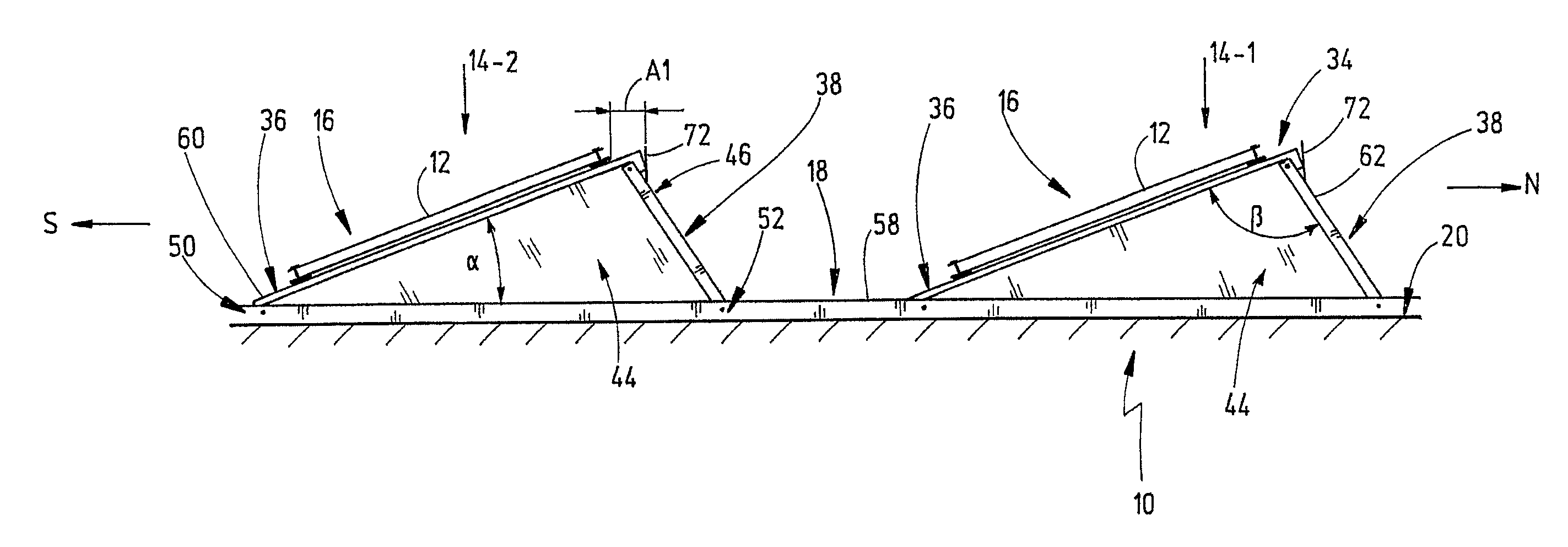
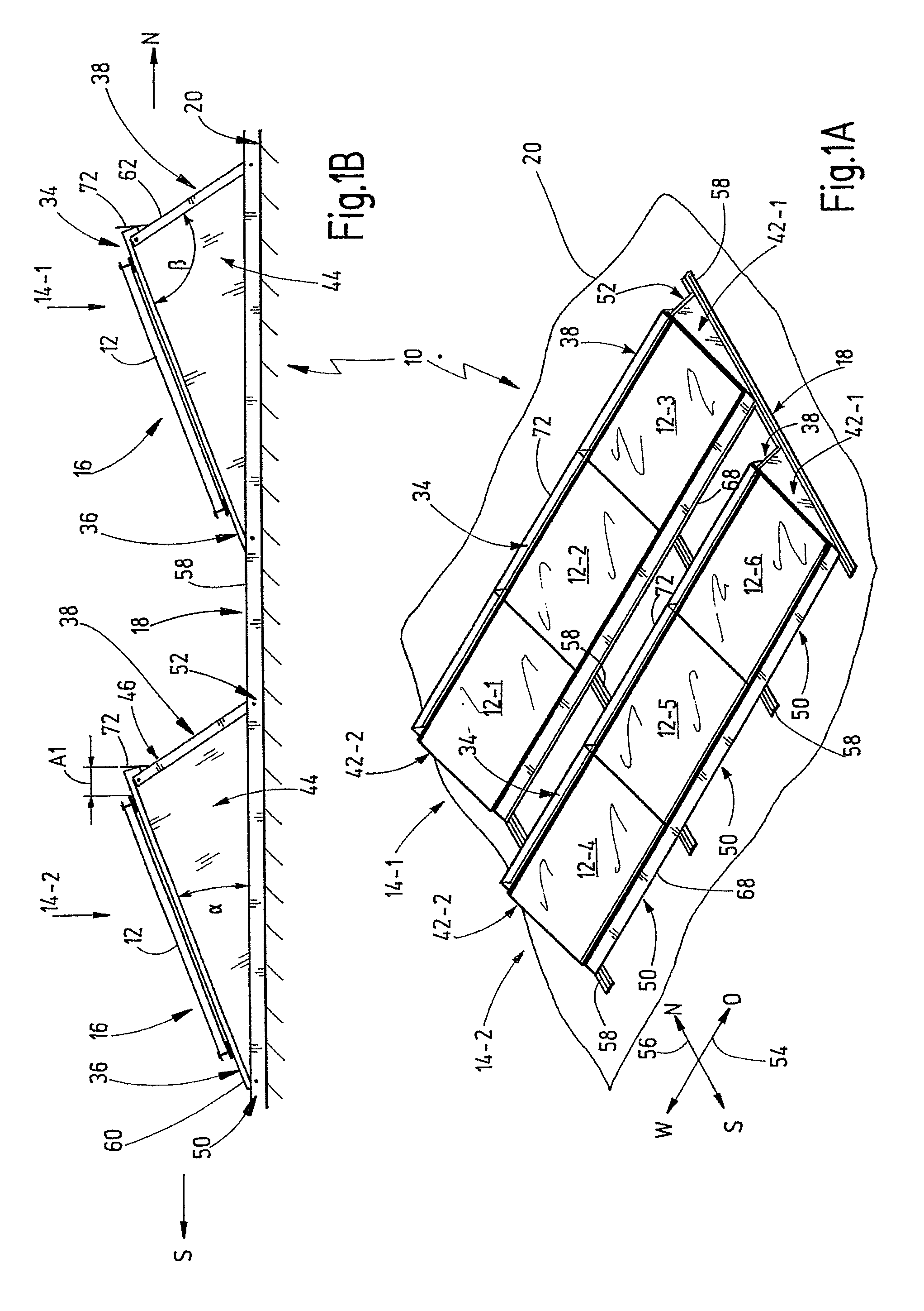
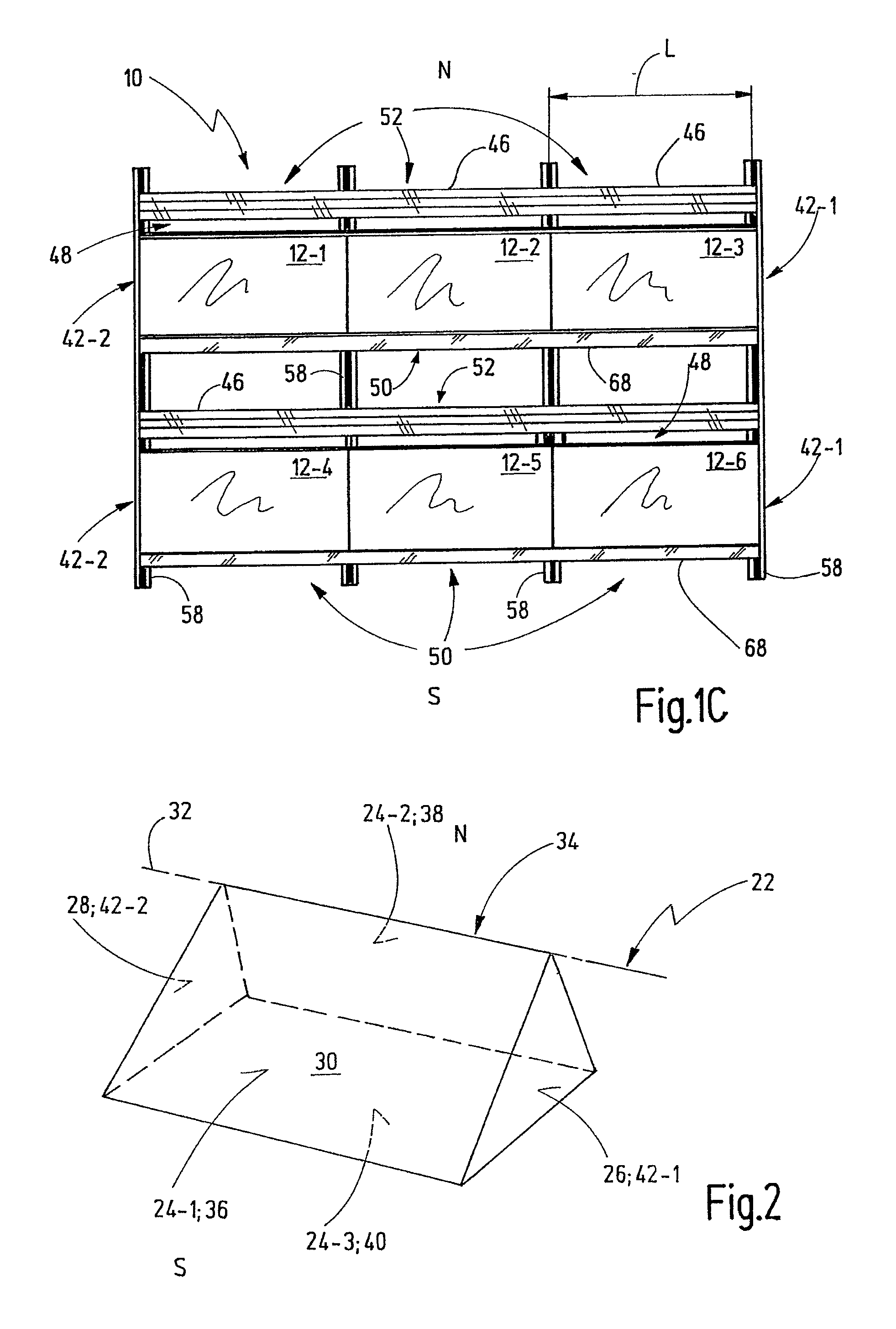
[0037]The present invention relates to a mounting system 10 which will be described hereinafter with common reference to the FIG. 1A to FIG. 1C in combination with FIG. 2. FIG. 1A shows a perspective view of the mounting system 10, when viewed obliquely from above. FIG. 1B shows a side view of the mounting system 10 of FIG. 1A along an east-west direction. FIG. 1C shows a top view on the mounting system 10 of the FIGS. 1A and 1B in a north-south direction. FIG. 2 shows a possible base shape of the mounting system 10 of FIG. 1 in terms of a prism. A prism is a geometrical body having a multi-cornered base area, the side edges of the body being parallel and typically having the same length. A prism is generated by parallel displacement of a polygon along a straight line in space, which does not lie in this plane, and therefore is a special polyhedron. Most of the prisms have a triangle as base and cover areas, as will be explained in more detail below. Other shapes are based, for exam...


PUM


Abstract

A mounting system for positioning at least one photovoltaic module of a PV-module unit on a planar flat roof in an inclined position defining an angle with the flat roof, comprising: a frame, wherein the frame defines a PV-module unit mounting side, a back side, two lateral sides, and a bottom side, which commonly define a prism, the base area of which corresponds to one of the lateral sides, the cover area of which corresponds to the other one of the lateral sides, and a jacket area of which corresponds to the mounting side, the back side and the bottom side. The mounting and back sides intersect along an imaginary line which defines a ridge arranged oppositely to the bottom side. A wind deflector may be attached to the back side such that an open ridge gap is formed and connects an interior of the prism to the environment.

Description

CROSS REFERENCE TO RELATED APPLICATIONS[0001]The present application claims the priority under the Paris Convention of the German patent application DE 10 2011 109 772.8 filed on Aug. 4, 2011. The entire content of this application is incorporated herewith by reference.BACKGROUND OF THE INVENTION[0002]The present invention relates to a mounting system for positioning at least one photovoltaic module (hereinafter also designated briefly as “PV module”) of a PV-module unit on a planar flat roof in a position defining an angle (alpha) with the flat roof.RELATED PRIOR ART[0003]Conventional flat-roof mounting systems exist which are open laterally and to the back, wherein a baffle plate is positioned behind the system, perpendicular to the roof, for avoiding wind from reaching below the PV module, which is blowing from the direction of the back side. These systems are laterally open.[0004]Further, systems exist which are formed in an apron-like shape and which are guided around the mount...

Claims


Application Information

Patent Timeline
IPC IPC(8): H01L31/0203
CPCH02S20/24Y02B10/12F24S25/13F24S25/16F24S40/85F24S2025/02Y02B10/10Y02B10/20Y02E10/47Y02E10/50
Inventor WALZ, LEOJOHNER, FABIAN
Owner CREOTECC
Why Eureka
Try Eureka