Ball arm switching shower

a shower and ball arm technology, applied in the field of showers, can solve problems such as inconvenience in operation, and achieve the effects of convenient operation, simple structure, and user-friendly operation

Active Publication Date: 2013-02-07
XIAMEN SOLEX HIGH TECH IND CO LTD
View PDF11 Cites 8 Cited by
  • Summary
  • Abstract
  • Description
  • Claims
  • Application Information

AI Technical Summary

Benefits of technology

[0030]1 The switching plate is driven to swing and slide through the movement of the handle, the movement of the sealing piece is controlled to open or close the water division hole through switching the slide and the swing of the switching plate, so that the switching communication of the water division hole and the water inlet passage is achieved, therefore: a. one hand operation can be achieved with obvious gears feeling when switching, and the users are prevented from faulty operation, and the operation is convenient; b. the switching mechanism can switch four outlet functions with simple structure;
[0031]2 A cross straight slot is opened on the screens board, therefore: a. the opening of the assembling slot can be covered by the screens board and can locate the connecting part; b. the cross straight slot can ensure the operation accuracy of the handle; c. it can avoid that water comes out of two outlet functions simultaneously;
[0032]3 The locating pin is inserted in the first locating slot to achieve the maintaining of the switching state with simple structure and better switching hand feel;
[0033]4 When the switching plate is swinging, the first touching end is against the first control part, so that the first sealing piece inclines, the first sealing part is lifted up, and then the water division hole corresponding with the first sealing piece is communicated with the water inlet passage, the structure is novel and simple;
[0034]5 When switching plate is sliding, the second touching end is against the second control part, so that the second sealing piece inclines, the second sealing part is lifted up, and then the water division hole corresponding with the second sealing piece is communicated with the water inlet passage, the structure is novel and simple.

Problems solved by technology

Because the switch of the two traditional switching mechanisms must be operated by two hands, it is inconvenient to operate when two hands is stained with bubbles during shower.

Method used


Image

  • Ball arm switching shower
  • Ball arm switching shower
  • Ball arm switching shower

Examples


Embodiment Construction

[0063]With the following description of the drawings and specific embodiments, the invention shall be further described in details.

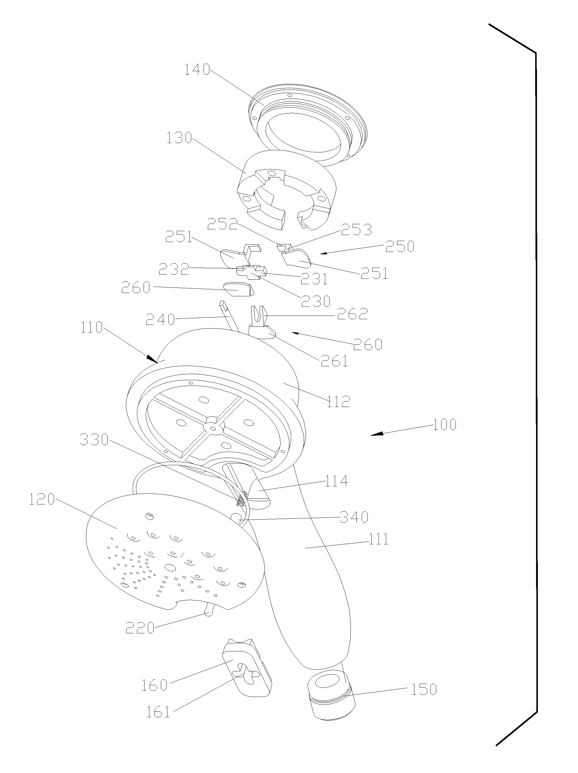
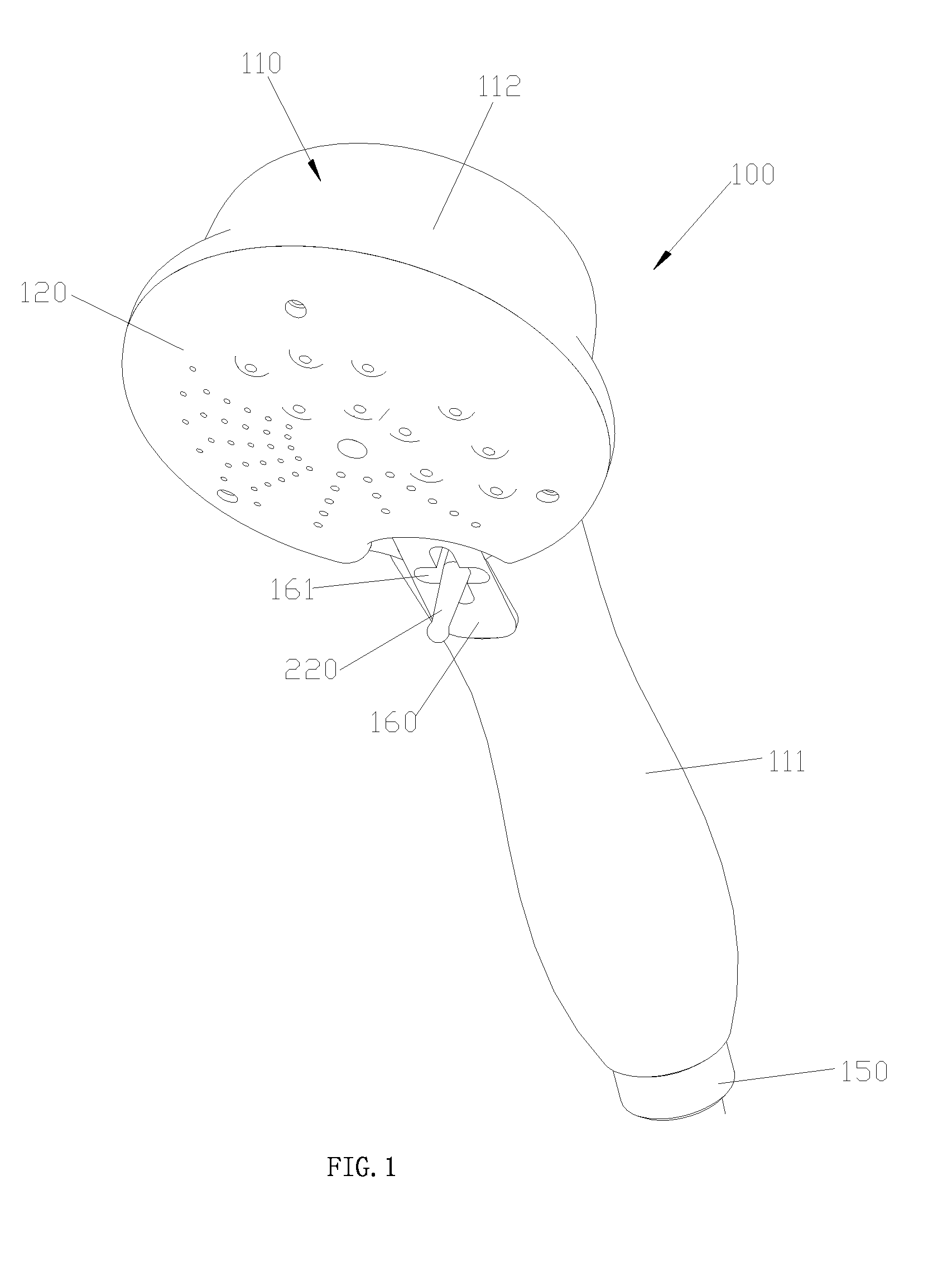
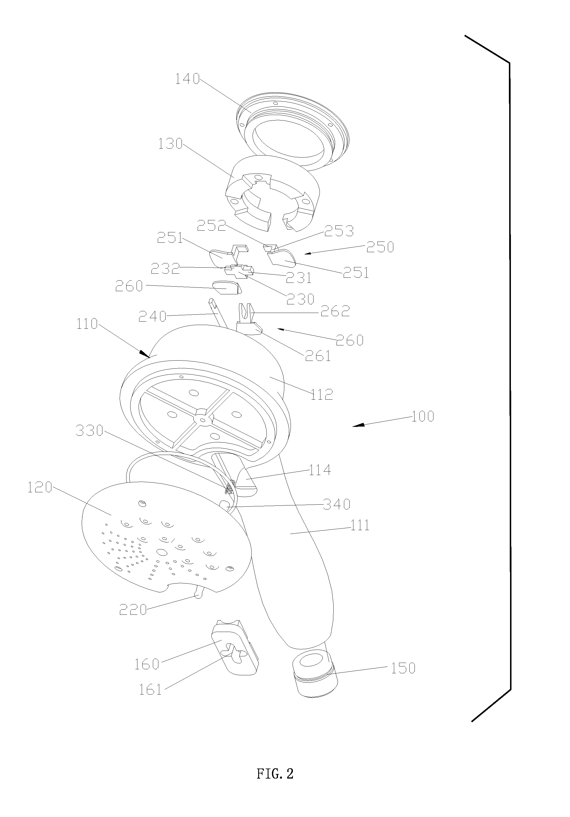
[0064]According to FIG. 1 to FIG. 28, the ball arm switching shower comprises a fixed unit 100 and a switching mechanism. According to FIG. 1 to FIG. 3, FIG. 8 to FIG. 16, the fixed unit 100 comprises a body 110, a face cover 120, a locating plate 130, a top cover 140, a plug 150 and a screens board 160.

[0065]The body 110 is provided with a handheld part 111 and a solid joint head 112 fixedly connected to the handheld part 111. A fixing slot 113 is concavely arranged at the back of the solid joint head 112, and an assembling slot 114 is concavely arranged on the front of the body 110, and a communicating slot 115 communicating the fixing slot 113 with the assembling slot 114 is also arranged in the body 110, and the bottom surface of the assembling slot 114 is a cambered surface. A water inlet passage is also opened in the body 110, the inner end of the ...


PUM


Abstract

A ball arm switching shower has a fixed unit and a switching mechanism. The fixed unit is provided with multiple outlet functions, a assembling slot and a water inlet passage, each outlet function is provided with a water division hole. The switching mechanism comprises a connecting part, a handle, a switching plate, a transmission shaft and a sealing piece. The connecting part can be mounted in the assembling slot in a sliding and swinging manner. The handle is fixedly connected to the connecting part. The transmission shaft can fixedly connect to the connecting part and the switching plate, so that the switching plate can be driven to swing and slide through the movement of the handle.

Description

FIELD OF THE INVENTION[0001]The present invention relates to a shower, more particularly to a ball arm switching shower.BACKGROUND OF THE INVENTION[0002]The switching shower usually comprises a fixed unit and a switching mechanism, the fixed unit is provided with multiple outlet functions, each outlet function is provided with one water division hole. There are two kinds of traditional switching mechanism: the first kind is rotary switch, the switch of the water division holes is achieved through the relative rotation between the water division body of the switching mechanism and the fixed unit, and then the switch of outlet functions is achieved; the second kind is sliding switch, the switch of the water division holes is achieved through the relative sliding between the water division body of the switching mechanism and the fixed unit, and then the switch of outlet functions is achieved. Because the switch of the two traditional switching mechanisms must be operated by two hands, ...

Claims


Application Information

Patent Timeline
Patent Type & Authority Applications(United States)
IPC IPC(8): B05B1/18
CPCB05B1/1609B05B1/18B05B1/169Y10T137/86549
Inventor ZHOU, HUASONGLUO, SHUIYUANWU, CAILINCAO, BIN
Owner XIAMEN SOLEX HIGH TECH IND CO LTD
Why Eureka
Try Eureka