Constant frequency synthetic ripple power converter

a power converter and constant frequency technology, applied in the field of power converters, can solve the problems of jitter or phase noise of switching, the most difficult transition, and the circuit is often affected, and achieve the effect of converting from dcm mode into ccm very quickly

Active Publication Date: 2013-02-14
QUALCOMM INC
View PDF11 Cites 44 Cited by
  • Summary
  • Abstract
  • Description
  • Claims
  • Application Information

AI Technical Summary

Benefits of technology

The present invention provides a switching power converter that combines the benefits of hysteretic control and synthetic ripple signal generation with the advantages of operating at a constant frequency in CCM and being stable in various conditions. The converter can quickly switch from DCM mode to CCM without significantly affecting the regulated output voltage.

Problems solved by technology

The technical problem addressed in this patent text is the need for a switching power converter that combines the hysteretic control approach with synthetic ripple generation but operates at a desired constant frequency without the use of frequency control circuits. The current methods used in the prior art require complex and unstable control circuits, and often result in unstable operation and high amplitude noise. The invention aims to solve this problem by introducing a new method for controlling system stability in all conditions.

Method used


Image

  • Constant frequency synthetic ripple power converter
  • Constant frequency synthetic ripple power converter
  • Constant frequency synthetic ripple power converter

Examples


Embodiment Construction
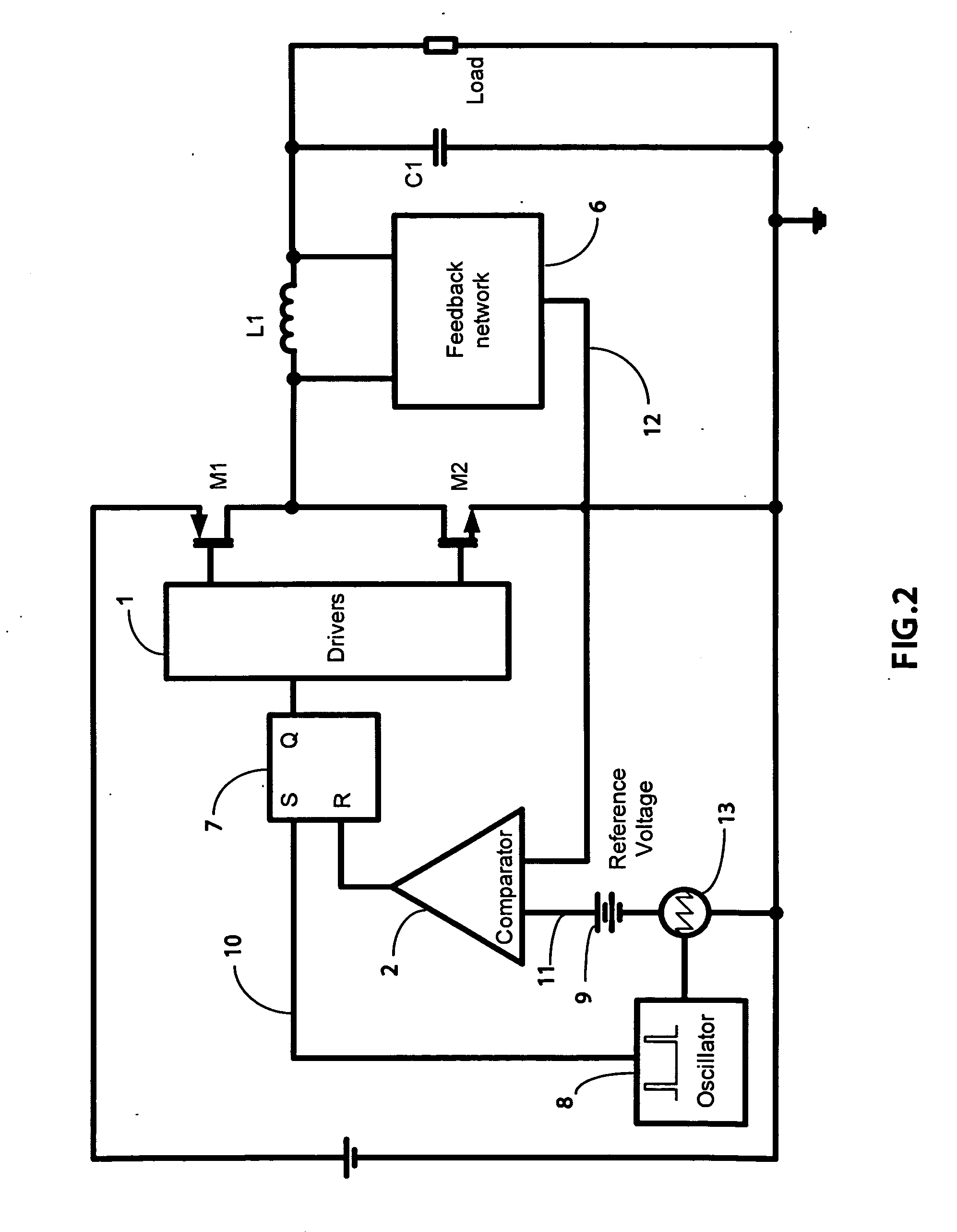
[0077]A FIG. 2

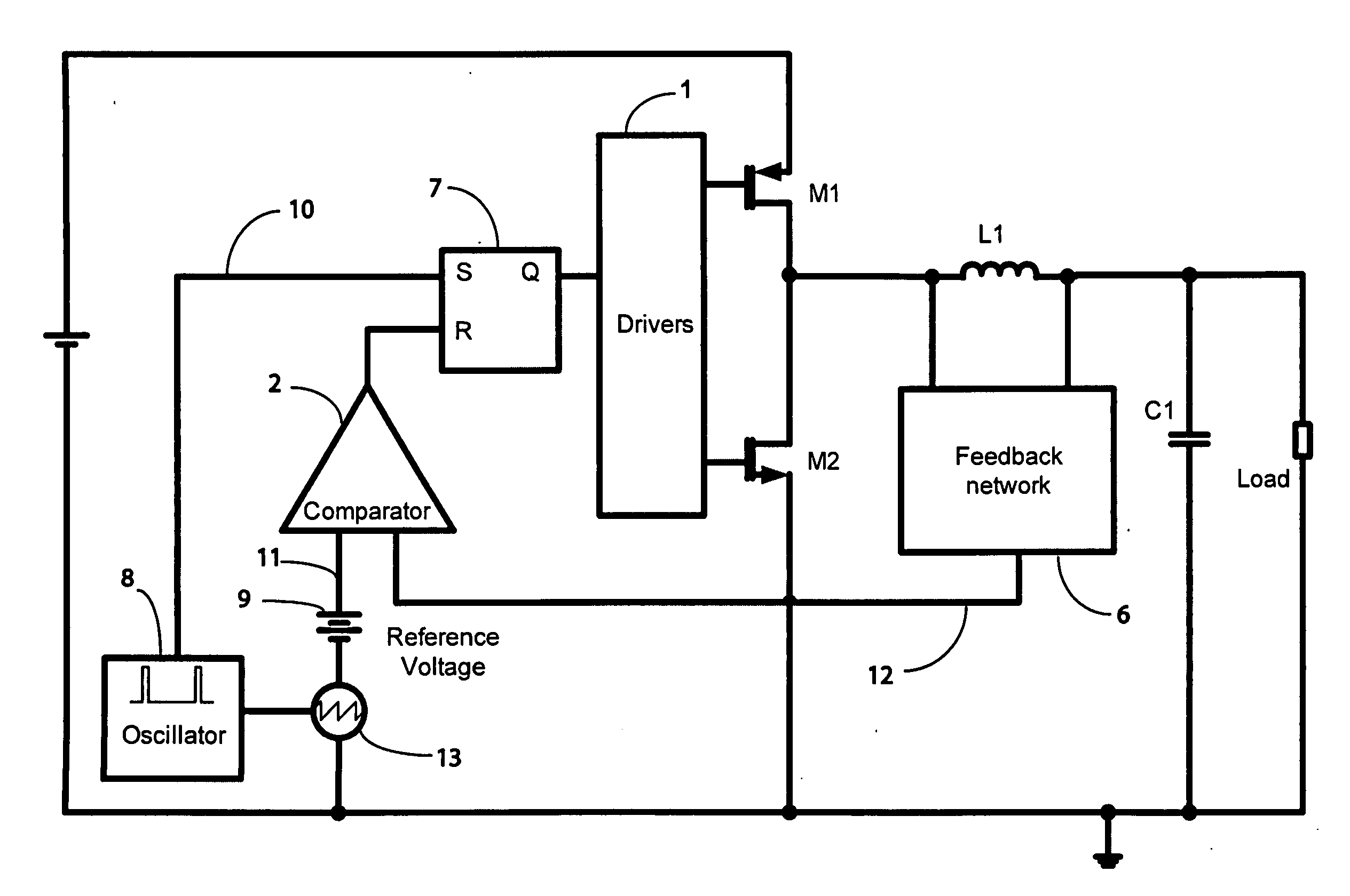
[0078]FIG. 2 shows the block diagram of the power converter according to the preferred embodiment of the present invention for a buck converter. The oscillator 8 generates a clock signal with a very small duty cycle to generate the ramp signal 13 and to synchronize the converter with the minimum off-time. The clock signal could also be generated externally to the power converter integrated circuit to synchronize the system to any desired frequency. The ramp signal generator 13 generates the saw tooth waveform (but it could as well generate a different shape ramp signal) synchronized to the clock signal 10. The ramp signal is in series to a reference voltage 9 (typically a bandgap reference voltage or any other DC voltage).

[0079]The resulting signal 11 feeds the comparator 2 that compares it with the synthetic ripple signal 12 coming from the feedback network 6. The feedback network 6 has the task to generate a ripple signal of the right amplitude and of the right bandw...


PUM


Abstract

A novel method to operate synthetic ripple switching power converters at constant frequency is presented. The method includes the generation of a clock signal and the summing of a ramp signal to a DC voltage reference to be compared to a synthetic ripple signal. The ramp signal is synchronous with the clock signal. A minimum on-time or minimum off-time type of control is implemented. The switching frequency is constant.
The presented approach provides significant advantages with respect to the more traditional means of utilizing hysteretic approaches combined with frequency control circuits.
The switching frequency can be as high as the one obtained for a hysteretic power converter, the load and line transient response is comparable with or better than the one achieved with hysteretic approaches. The stability is obtained by adapting the slope of the ramp signal in order to obtain the adequate gain of the system.
The method is presented for buck and boost hysteretic high frequency switching power converters, but can be utilized also for buck-boost converters. The general method can be utilized also for multiphase switching power converters.
A non clocked variant of the novel circuit topology is also presented to improve load and line transient performance.

Description


Claims


Application Information

Patent Timeline
Owner QUALCOMM INC
Why Eureka
Try Eureka