Device for visually confirming forward direction

a technology for visually confirming devices and forward directions, applied in mirrors, instruments, vehicle components, etc., can solve problems such as easy contamination or damage of reflecting mirrors, and achieve the effects of narrowing the field of vision, simple structure, and high visibility

Active Publication Date: 2013-02-14
HONDA MOTOR CO LTD
View PDF12 Cites 13 Cited by
  • Summary
  • Abstract
  • Description
  • Claims
  • Application Information

AI Technical Summary

Benefits of technology

[0028]According to the aspect described in (1), since the image of the forward side of the vehicle that is reflected in the first reflecting mirror disposed on the dashboard is reflected by the second reflecting mirror disposed on the lower side of the dashboard so as to be visually recognized by a crew member, the first reflecting mirror and the second reflecting mirror can be disposed at sufficiently low positions not narrowing the field of vision of the crew member. Thus, according to the present invention, high visibility can be acquired through a simple structure in which high-cost components are not used.
[0029]In addition, in the above-described aspect, the second reflecting mirror that reflects the reflected image of the first reflecting mirror is arranged on the lower side of the dashboard, and accordingly, the first reflecting mirror can be disposed at a sufficiently low position on the dashboard. Accordingly, even in a vehicle designed to have a large angle of forward inclination of the window shield glass, the first reflecting mirror can be arranged at a position located on the forward side of the inside of the vehicle at which the field of vision is not disturbed by a front pillar. Therefore, the visibility for the left and right sides of the forward side of the vehicle can be improved.
[0030]In the case of (2) described above, since the second light transmitting part is formed in the protruded part that protrudes from the dashboard to the inside of the vehicle and can be easily viewable, the crew member's visual recognition can be performed well. In addition, the second light transmitting part is formed on a face of the protruded part that faces almost in front of the crew member and is located on the backward side of the vehicle, the visible range in which the second reflecting mirror is viewed can be sufficiently secured while the area of the second light transmitting part is suppressed to a minimum.
[0031]In the case of (3) described above, since the first reflecting mirror is disposed on a face of the protruded part that is located on the forward side of the vehicle, the first reflecting mirror does not directly break into the eyes of the crew member, the visibility of the crew member for the forward side is improved, and the external display is improved.
[0032]In the case of (4) described above, since the first light transmitting part is disposed on the vehicle forward side of the protruded part, the first light transmitting part does not directly break into the eyes of the crew member, and the external display is improved.
[0033]In the case of (5) described above, since one of the first light transmitting part and the second light transmitting part is an opening that is disposed on the dashboard, the light transmitting part can be formed in an easy manner.

Problems solved by technology

In the case of this device for visually confirming a forward direction, since a structure is employed in which images reflected on the reflecting mirrors disposed outside the vehicle are directly visually confirmed by a crew member present on the inside of the vehicle, the images visually confirmed by the crew member are horizontally-reversed images so as to easily give a sense of discomfort to the crew member, and the reflecting mirrors may be easily contaminated or damaged.

Method used


Image

  • Device for visually confirming forward direction
  • Device for visually confirming forward direction
  • Device for visually confirming forward direction

Examples


first embodiment

[0123]Hereinafter, a first embodiment according to the present invention will be described with reference to the drawings.

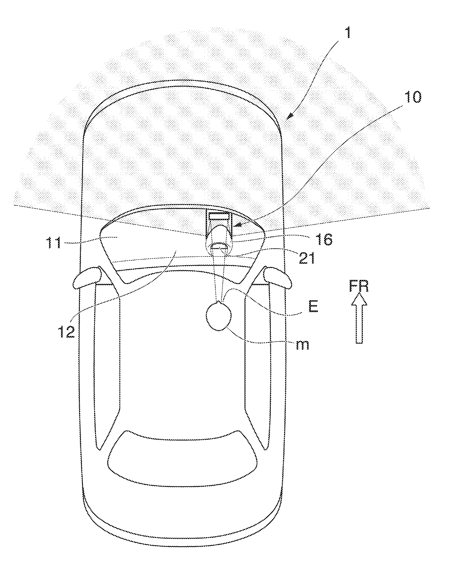
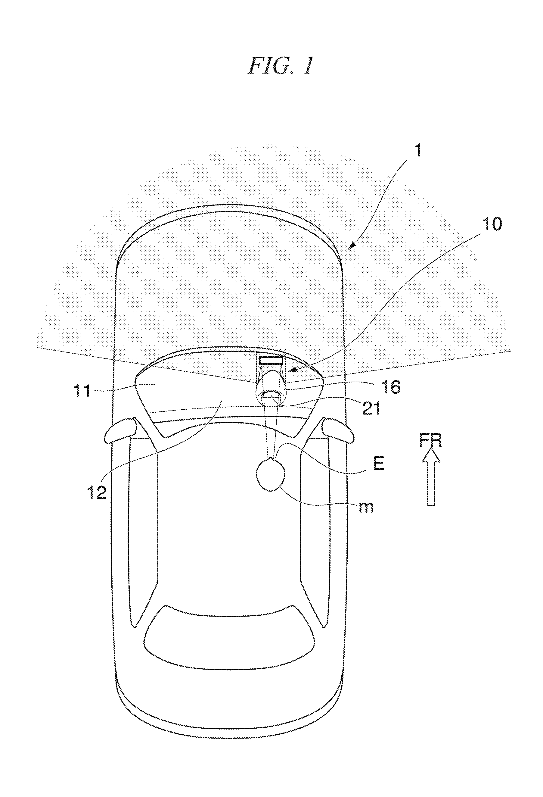
[0124]FIG. 1 is schematic view of a vehicle 1 that uses a device 10 for visually confirming a forward direction according to this embodiment, and FIGS. 2 to 4B are diagrams that illustrate a specific configuration of the device 10 for visually confirming a forward direction. In the figures, arrow FR represents a forward direction of the vehicle, and arrow UP represents an upward direction of the vehicle.

[0125]The device 10 for visually confirming a forward direction is arranged on the forward side of a driver's seat located inside the vehicle such that a crew member m seated on the driver's seat can visually confirm the lower side and the left / right side of a front portion of the vehicle 1 with his line of sight facing forward.

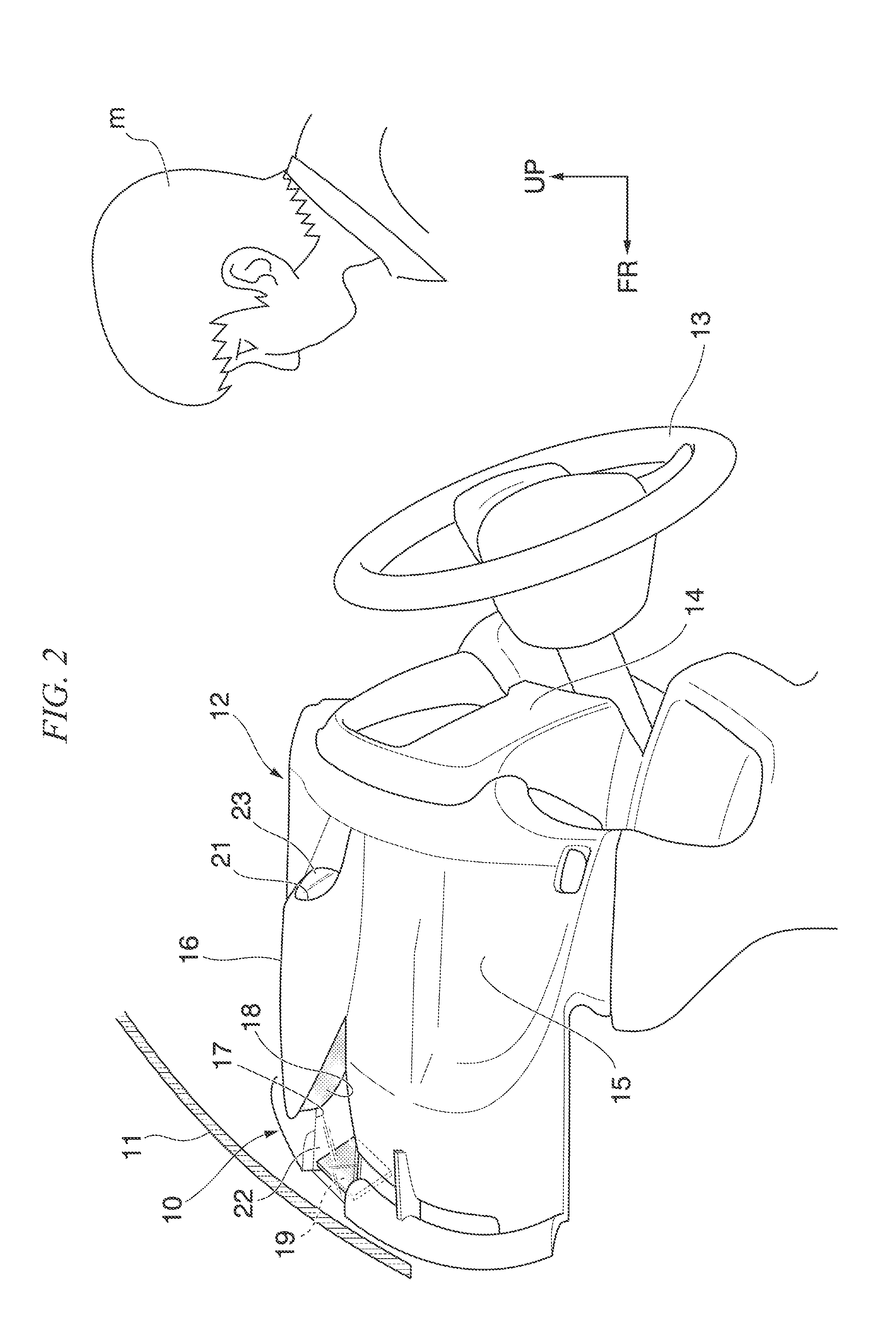
[0126]In FIGS. 2 and 3, reference numeral 11 is a window shield glass that is disposed so as to be forward sloped (sloped toward the lower...

second embodiment

[0152]Hereinafter, a second embodiment according to the present invention will be described with reference to the drawings.

[0153]FIG. 1 is a schematic diagram of a vehicle 1 that uses a device 10 for visually confirming a forward direction according to this embodiment, and FIGS. 2 to 6B are diagrams that illustrate specific configurations of the device 10 for visually confirming a forward direction. In the figures, arrow FR denotes a forward direction of the vehicle, and arrow UP denotes an upward direction of the vehicle.

[0154]The device 10 for visually confirming a forward direction is arranged on the forward side of a driver's seat located inside the vehicle such that a crew member m seated on the driver's seat can visually confirm the lower side and the left / right side of a front portion of the vehicle 1 with his line of sight facing forward.

[0155]In FIGS. 2 and 3, reference numeral 11 is a window shield glass that is disposed so as to be forward sloped (sloped toward the lower ...

third embodiment

[0183]Hereinafter, examples of a device for visually confirming a forward direction according to a third embodiment of the present invention will be described with reference to the drawings.

Example 1

[0184]First, the device for visually confirming a forward direction according to Example 1 of the present invention will be described with reference to FIGS. 1 to 18.

[0185]FIG. 1 is a schematic diagram of a vehicle 1 that uses a device 10 for visually confirming a forward direction according to Example 1, and FIGS. 2 to 6B are diagrams that illustrate specific configurations of the device 10 for visually confirming a forward direction. In the figures, arrow FR denotes a forward direction of the vehicle 1 and arrow UP denotes an upward direction of the vehicle 1.

[0186]The device 10 for visually confirming a forward direction is arranged on the forward side of a driver's seat located inside the vehicle such that a crew member m seated on the driver's seat can visually confirm the lower sid...


PUM


Abstract

A device for visually confirming a forward direction that allows a crew member to visually confirm a desired range on the forward side of a vehicle includes a first reflecting mirror that reflects the desired range and a second reflecting mirror that reflects a reflected image reflected on the first reflecting mirror toward the crew member, the first reflecting mirror is arranged on a dashboard that is located inside the vehicle, and the second reflecting mirror is arranged on a lower side of the dashboard, and a first light transmitting part and a second light transmitting part are disposed in an area that connects the first reflecting mirror and the second reflecting mirror and an area that connects the second reflecting mirror and an eye-point of the crew member.

Description

TECHNICAL FIELD[0001]The present invention relates to a device for visually confirming a forward direction, which indirectly visually confirms the forward side of a vehicle.[0002]Priority is claimed on Japanese Patent Application No. 2010-053751, filed Mar. 10, 2010, Japanese Patent Application No. 2010-114195, filed May 18, 2010, Japanese Patent Application No. 2010-100065, filed Apr. 23, 2010, Japanese Patent Application No. 2010-100066, filed Apr. 23, 2010, and Japanese Patent Application No. 2010-234582, filed Oct. 19, 2010, the content of which is incorporated herein by reference.BACKGROUND ART[0003]As devices for visually confirming a forward direction, devices are known in which imaging means is installed to a front portion of a vehicle, and an image that is imaged by the imaging means is projected to a monitor disposed inside the vehicle (for example, see Patent Document 1 and Patent Document 2).[0004]In devices of such a type for visually confirming a forward direction, whi...

Claims


Application Information

Patent Timeline
Patent Type & Authority Applications(United States)
IPC IPC(8): G02B17/06
CPCB60R1/006B60R1/10B60R1/04B60R1/082G02B5/10G02B17/0605
Inventor MATSUMOTO, YOSHIYUKIKISHIMOTO, YUYAUEMATSU, HIROSHIKUWASHIMA, YUJISASAKI, MIKUHASHIMOTO, TOSHIHIRO
Owner HONDA MOTOR CO LTD
Why Eureka
Try Eureka