Such reflections could be a potential safety
hazard.
The receivers described in the prior art may not be optimum for use in modern portable electronic devices, such as cellular phones and tablets, or even
laptop PCs, as they are generally too large, and especially too deep.
Furthermore, they may be unsuitable for use in the
consumer environment, since, given the power requirements of cellular phones and other portable
electronics devices, which is reflected in the
power level circulating in the distributed
laser cavity, they may not fulfil safety regulations.
This is particularly so in an environment where finger prints,
dirt, spilled liquids and the like are a reality of life, and their presence on the surface of the light receiving element of the
receiver may compromise any safety measures taken to prevent stray laser emission.
Unless the thickness is limited to that of these devices, typically 6 mm, the receiver solution may not be commercially acceptable.
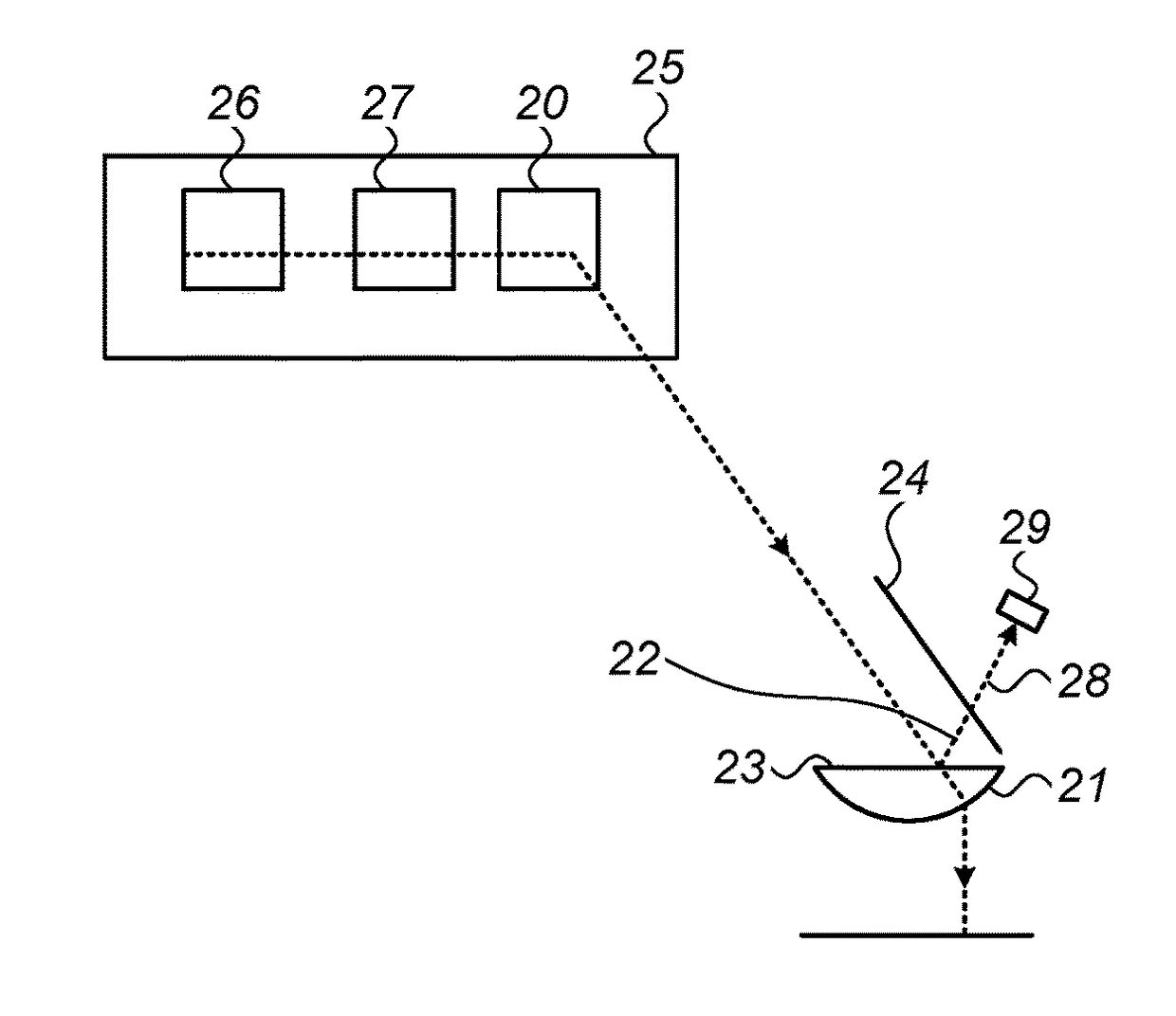
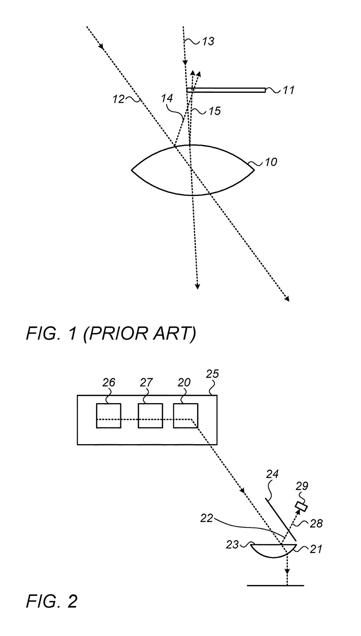
With regard to criterion (b), the front surface of the optical input element of such devices, on which light impinges before entering the receiver, is a particularly problematic feature, since reflections from that front surface may be a main source of safety problems with the receiver.
Such systems are limited in the amount of power they could safely transmit, as some of the power will always be reflected by the front surface.
Reflections from the front surface represent a
power loss, and losses reduce the
system's efficiency dramatically as they compete with output
coupling.
However, the use of an AR
coating on a domestically used device such as a cellphone is problematic, since in such a
consumer environment,
dirt, spilled liquids, dust, fingerprints, and similar
layers on top of the AR coating will amend the effectiveness of the AR coating, leading to higher reflections, and secondly, may eventually lead to degradation and peeling of the AR coating, again compromising safety.
Other alternative solutions have been proposed, but each of these solutions has its own disadvantages:1. Increasing the
beam diameter so much that reflection from the receiver lens would be at a size and intensity so that it would be safe.
However, using this technique, the size of the beam needed to transmit the power required by a
mobile device may be bigger than the entire area available for a receiver on the
mobile device!
Such a beam block height would have a very significant
impact on the overall receiver height.3. Diffusing the beam impinging on the receiver lens front surface—however this solution is not suitable for use inside a laser resonator, as it would distort the laser beam in a way that would not allow the wave front to be recreated after a round trip.
This also increases the overall depth of the receiver, which is disadvantageous for such an application.
It is clear that the prior art positioning and configuration of the photovoltaic
cell(s) has a number of disadvantages, the trade-off between which is always a compromise to performance.
Most anti-reflection coatings, especially those with very low
reflectivity of the order of 0.1% or better, cannot withstand typical use by a domestic user, such as normal
scratching, or
wear and tear.
However, such a level of reflected light creates a
safety risk unless properly blocked or diffused and will also reduce
system efficiency significantly.
The positioning of the
output coupler on the front
optical surface of the receiver, as used in the systems of the present application, has the
disadvantage that the output coupled light is extracted from two beams coming from unknown positions on the front surface, in unknown directions, and which are difficult to collect and to direct onto a photovoltaic
cell.
In conventional laser design, the number of surfaces inside the laser resonator is reduced as much as possible, since each additional surface creates an additional loss in both the forward and
backward propagation direction of the
laser light, and those losses are in competition with the output
coupling and thus may reduce efficiency significantly.
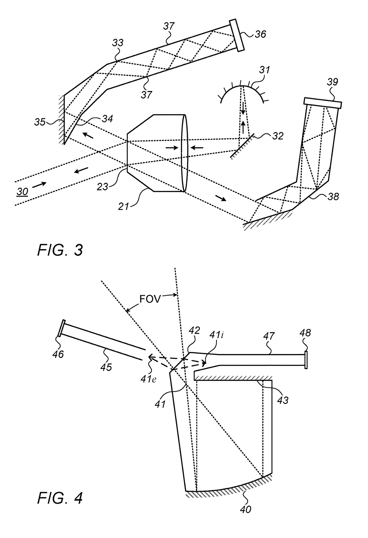
Placing the
pupil near the front surface reduces the
field of view and significantly limits the possible optical designs that could be used.
Furthermore, a requirement that the front surface be flat, or nearly flat, typically causes aberrations that reduce
system performance.
The output
coupling level in prior art conventional laser systems is typically adjusted to provide optimal performance of the
gain medium, this resulting in maximal lasing efficiency.
. . beyond which the cavity is overloaded, so that total cavity losses exceed the available
gain, and no oscillation is possible.
. . , however, the mirror transmission decreases faster than Icirc increases, and the
power output decreases, eventually becoming zero at zero transmission through the end mirrors.
The laser at this point is, of course, still oscillating—in fact, oscillating the strongest of all—but with all its available power being uselessly dissipated in the
internal cavity losses.
It is also apparent that the optimum output coupling is always considerably smaller than the available gain, and that even very small internal losses have a very serious effect on the maximum useful output power available from the laser.”
This in turn would make the transmitter large, expensive and slow to focus.

