Camera module
a technology of camera module and module body, which is applied in the field of camera module, to achieve the effect of reducing the risk of oscillation of a servo system and reducing the vibration of elastic members
- Summary
- Abstract
- Description
- Claims
- Application Information
AI Technical Summary
Benefits of technology
Problems solved by technology
Method used
Image
Examples
embodiment 1
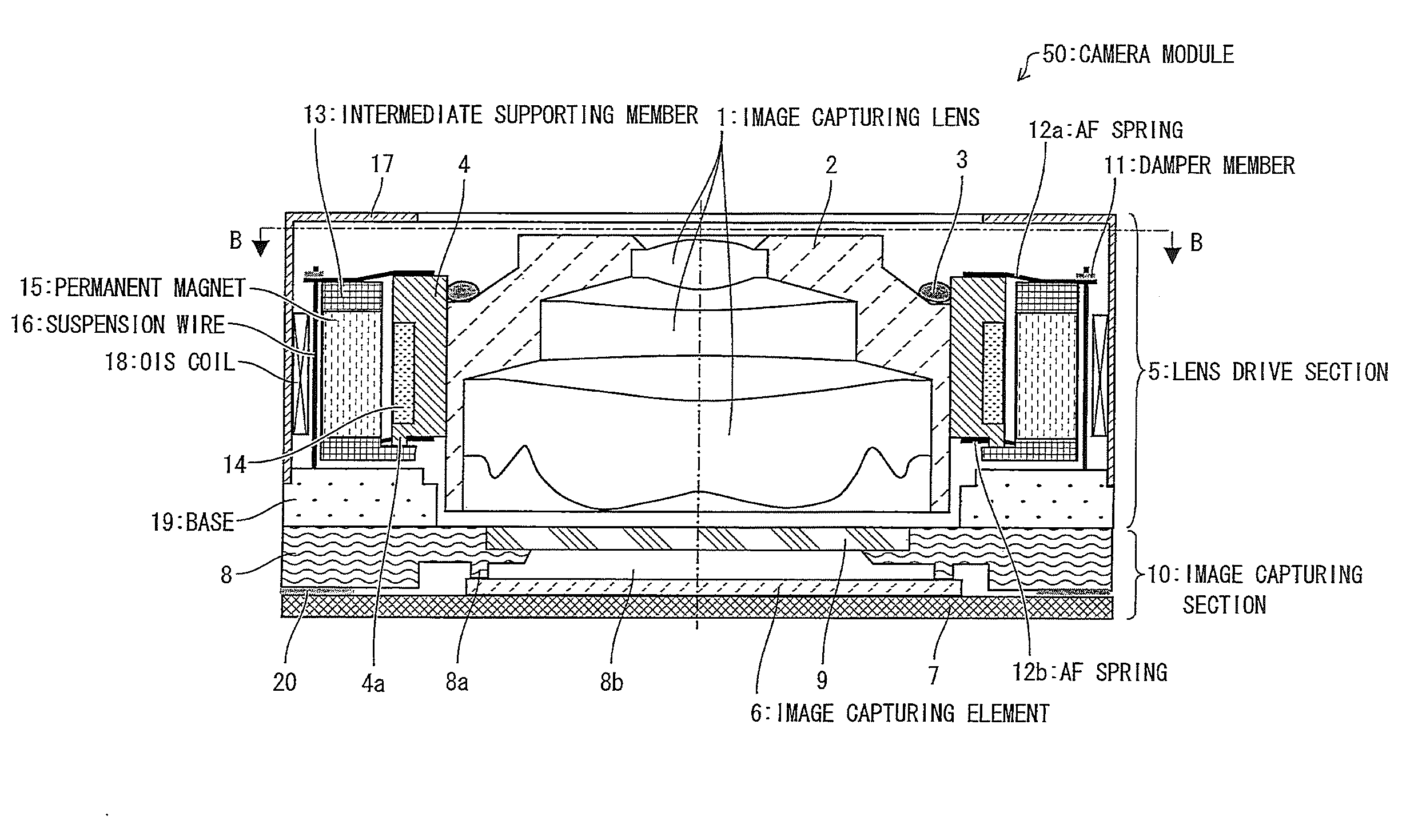
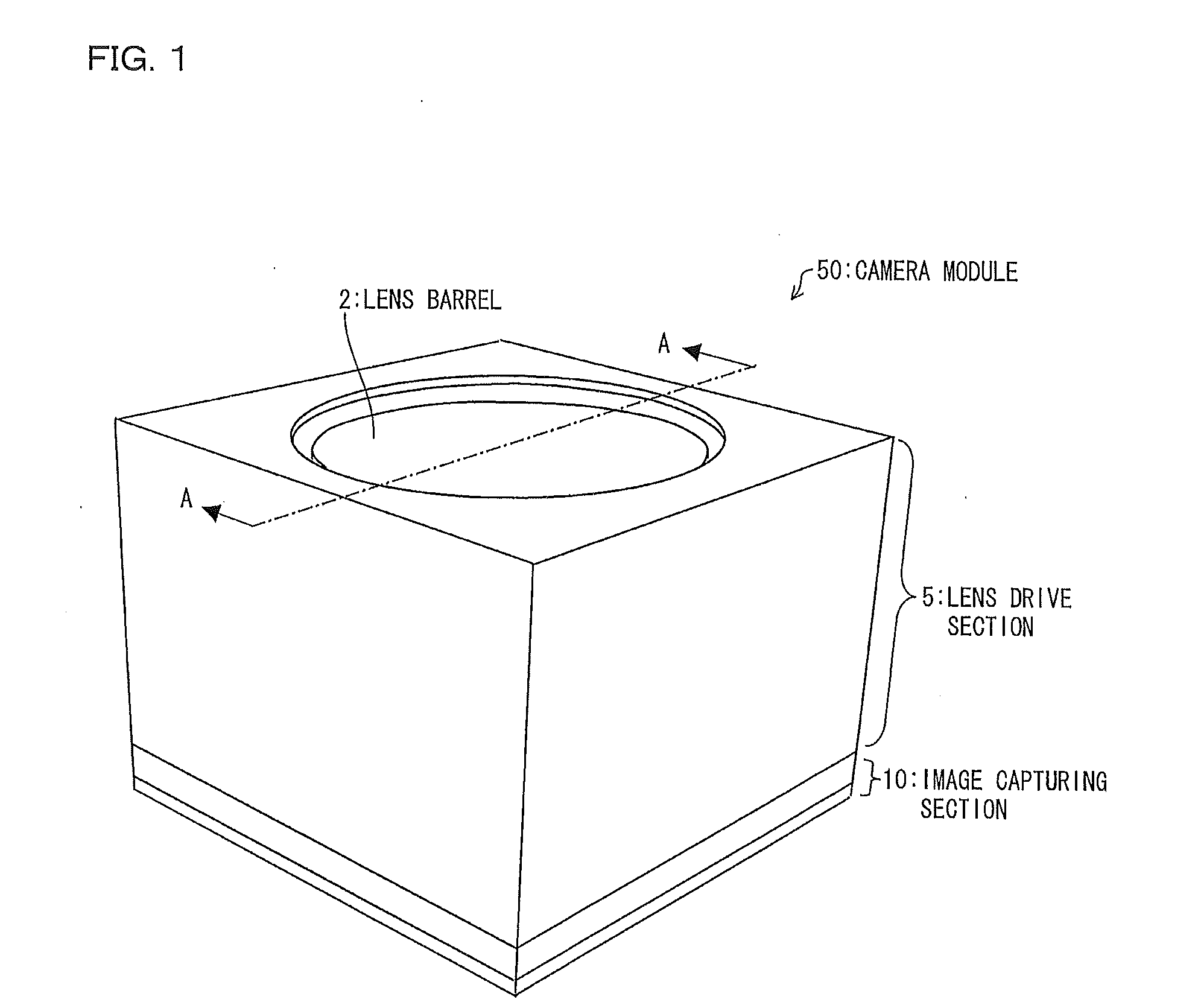
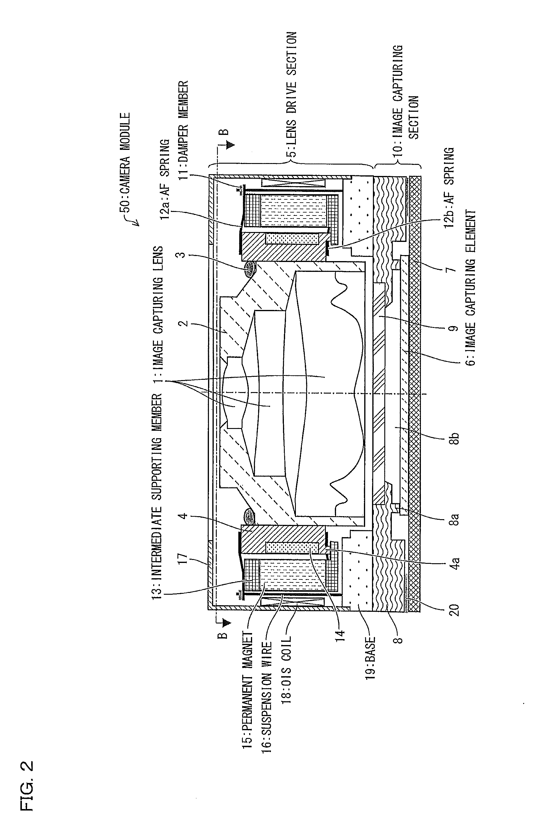
[0034]FIG. 1 is a perspective view schematically illustrating a configuration of a camera module 50 in accordance with Embodiment 1 of the present invention. FIG. 2 is a cross-sectional view taken along the line A-A of the camera module 50 illustrated in FIG. 1. FIG. 3 is a cross-sectional view taken along the line B-B of the camera module 50 illustrated in FIG. 2.
[0035](Camera Module)
[0036]As illustrated in FIGS. 1 through 3, the camera module 50 includes (i) image capturing lenses 1, (ii) a lens barrel 2 accommodating the image capturing lenses 1, and (iii) a lens holder 4 fixing the lens barrel 2 in the camera module 50 with the use of an adhesive 3.
[0037]The camera module 50 further includes (i) a lens drive section 5 for moving the image capturing lenses 1 in a direction of an optical axis of the image capturing lenses 1 (hereinafter, referred to as the optical-axis direction) and in directions of two axes each perpendicular to the optical-axis direction and (ii) an image captu...
embodiment 2
[0080]According to Embodiment 1, an arm part 12c, via which a suspension wire 16 and an OIS moving part are connected, functions as an elastic member for suppressing stress to be applied to the suspension wire 16. The present invention is, however, not limited to such. For example, it is possible to cause a connecting part, via which a suspension wire 16 and an OIS fixed part are connected, to function as an elastic member for suppressing stress to be applied to the suspension wire 16. The following description will discuss such a configuration as Embodiment 2 of the present invention.
[0081]FIG. 10 is a cross-sectional view schematically illustrating a configuration of a camera module 50 in accordance with Embodiment 2. FIG. 11 is an enlarged view illustrating a configuration, in the camera module 50, of an area around one of connecting parts of a suspension wire 16 and an OIS fixed part. Note that, in Embodiment 2, members whose functions are the same as those of Embodiment 1 are g...
embodiment 3
[0087]The following description will discuss how to better provide a damper member 11, while contrasting between an example configuration A illustrated in (a) of FIG. 12 and an example configuration B illustrated in (b) of FIG. 12. Both of (a) and (b) of FIG. 12 are cross-sectional views each taken along the line C-C drawn in FIG. 3. Hereinafter, (i) a part of a suspension wire 16, which part is connected to an arm part 12c, is referred to as a moving-part-side fixed end or as a first connecting part 16a, (ii) a part of the suspension wire 16, which part is connected to a base 19 is referred to as a fixed-part-side fixed end or as a second connecting part 16b, and (iii) a part of the suspension wire 16 between the first connecting part 16a and the second connecting part 16b is referred to as a flexible part 16c. The flexible part 16c bends in response to a movement of an OIS moving part.
[0088]In both the example configurations A and B, the suspension wire 16 (i) goes through an open...
PUM
 Abstract
Description
Claims
Application Information
 - R&D
- Intellectual Property
- Life Sciences
- Materials
- Tech Scout
- Unparalleled Data Quality
- Higher Quality Content
- 60% Fewer Hallucinations
Browse by: Latest US Patents, China's latest patents, Technical Efficacy Thesaurus, Application Domain, Technology Topic, Popular Technical Reports.
© 2025 PatSnap. All rights reserved.Legal|Privacy policy|Modern Slavery Act Transparency Statement|Sitemap|About US| Contact US: help@patsnap.com


