Heat dissipation device with mounting structure

a technology of heat dissipation device and mounting structure, which is applied in the direction of basic electric elements, semiconductor devices, lighting and heating apparatus, etc., can solve the problems of increasing the difficulty of overcoming the problem of cooling an electronic device, damage or even burnout of the whole electronic device, and avoiding undesirable heat generation by the size-reduced electronic elements, so as to avoid undesirable heat generation, avoid undesirable

Inactive Publication Date: 2013-02-21
ASIA VITAL COMPONENTS SHENZHEN CO LTD
View PDF9 Cites 3 Cited by
  • Summary
  • Abstract
  • Description
  • Claims
  • Application Information

AI Technical Summary

Benefits of technology

[0013]The heat dissipation device with mounting structure according to the present invention not only enables tight attachment of the heat dissipation device to heat-generating elements to avoid undesirable thermal resistance, but also ensures vacuum tightness of the chamber in the main body to avoid undesirable leakage of working fluid from the chamber because the mounting elements do not penetrate through the main body to cause damage to the chamber.
[0014]Therefore, the present invention provides the following advantages: (1) it can be tightly attached to the heat-generating elements to avoid thermal resistance; (2) it does not cause leakage of working fluid from the chamber of the main body; and (3) it has prolonged service life.

Problems solved by technology

However, heat generated by the size-reduced electronic elements forms a main hindrance to the good performance of the compact electronic devices.
With the increased heat flux, it becomes more difficult to overcome the problem of cooling an electronic device.
The increase of heat flux would cause overheat of the electronic device at different time and over different length or size of the device, and might cause damage to or even burnout of the whole electronic device.
However, the vacuum space being extended through by the copper posts loses its vacuum tightness and is no longer in a vacuum state.
Further, the copper posts extended through the vacuum space would inevitably form an impediment in the flow path of the working fluid filled in the vacuum space to thereby cause reduction in the heat transfer efficiency of the vapor chamber.
In some worse conditions, the working fluid might leak out of the vacuum space to result in a useless vapor chamber.
In brief, the vapor chamber with the conventional mounting structure is subjected to the following problems: (1) there would be a thermal resistance between the vapor chamber and the heat source; and (2) the vapor chamber might have reduced heat transfer efficiency.

Method used


Image

  • Heat dissipation device with mounting structure
  • Heat dissipation device with mounting structure
  • Heat dissipation device with mounting structure

Examples


Embodiment Construction

[0024]The present invention will now be described with some preferred embodiments thereof and with reference to the accompanying drawings. For the purpose of easy to understand, elements that are the same in the preferred embodiments are denoted by the same reference numerals.

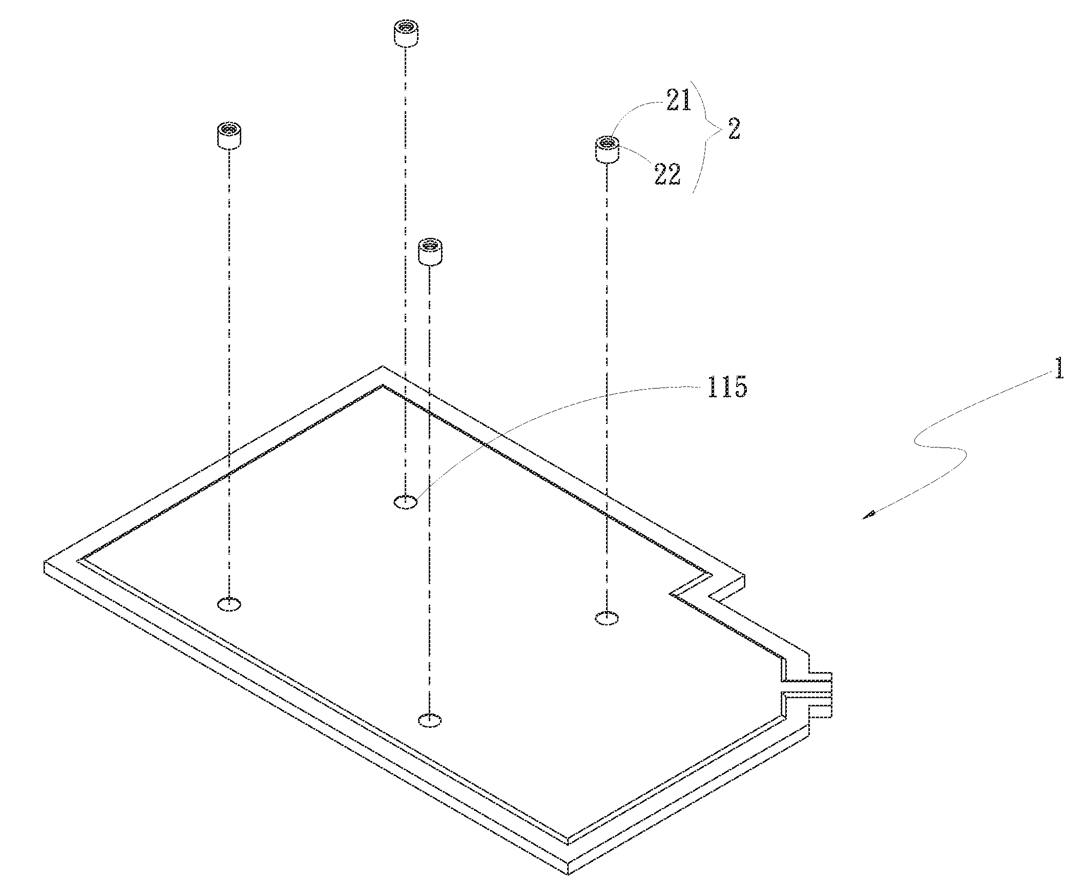
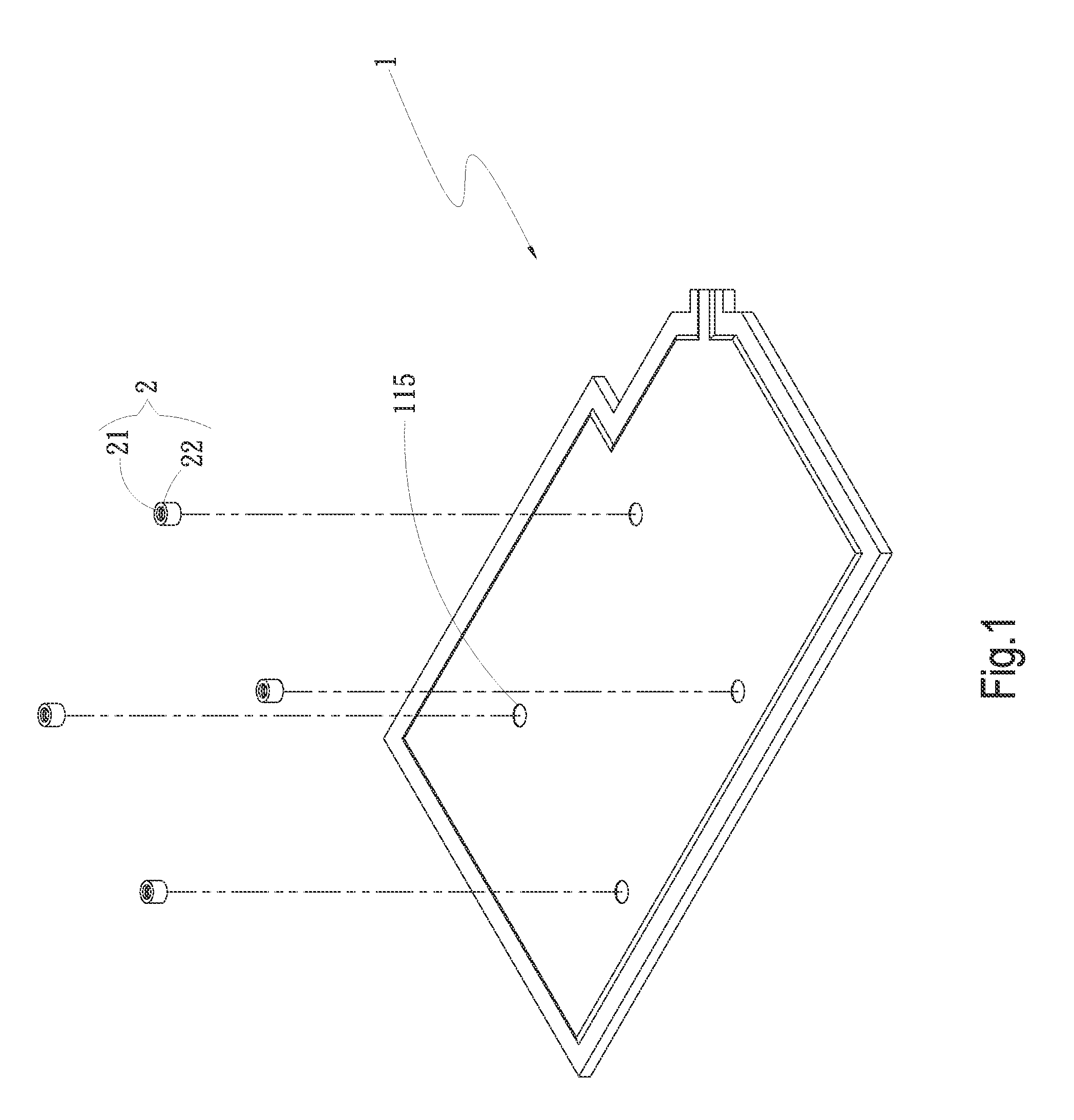
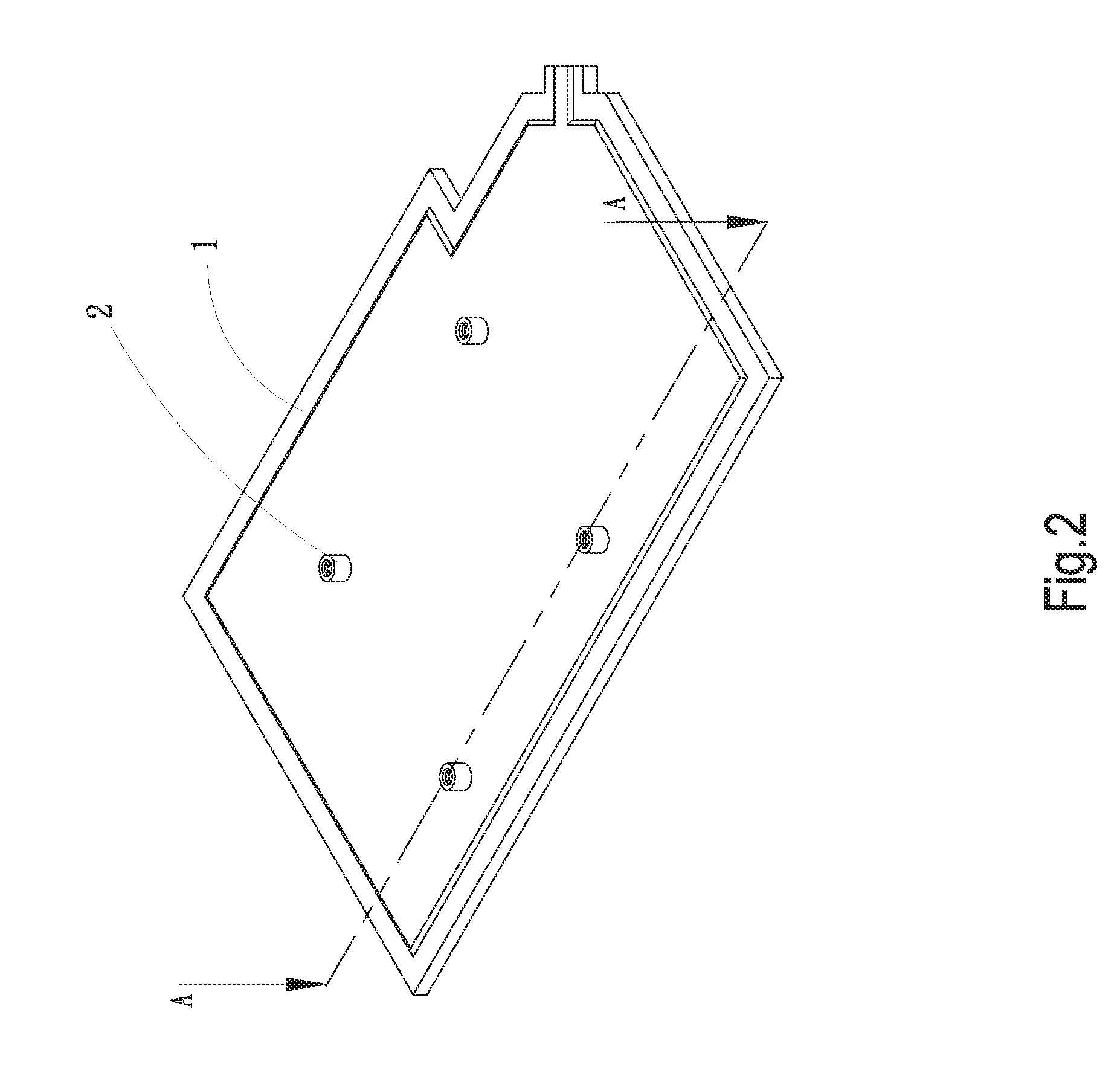
[0025]Please refer to FIGS. 1 and 2 that are exploded and assembled perspective views, respectively, of a heat dissipation device with mounting structure according to a first embodiment of the present invention; and to FIG. 3 that is a sectional view taken along line A-A of FIG. 2. As shown, the present invention in the first embodiment includes a main body 1 and a plurality of mounting elements 2.

[0026]The main body 1 includes an internally defined chamber 11 having a first side 111 and an opposite second side 112; a plurality of supports 113 located in the chamber and respectively having two ends connected to the first side 111 and the second side 112 of the chamber; a working fluid 3 filled in the chamber 11...


PUM


Abstract

A heat dissipation device with mounting structure includes a main body and a plurality of mounting elements. The main body includes an internally defined chamber having a first side and an opposite second side; a plurality of supports located in the chamber and respectively having two ends connected to the first side and the second side of the chamber; a working fluid filled in the chamber; and a plurality of connection sections in the form of recesses formed on an outer surface of the main body at positions corresponding to the supports in the chamber. The mounting elements are connected to the connection sections. With these arrangements, the heat dissipation device with the mounting elements connected to one outer surface thereof can maintain the chamber in the main body in an airtight state and ensure tight contact of it with a heat-generating element.

Description

[0001]This application claims the priority benefit of Taiwan patent application number 100129389 filed on Aug. 17, 2011.FIELD OF THE INVENTION[0002]The present invention relates to a heat dissipation device with mounting structure, and more particularly to a heat dissipation device that has mounting elements connected thereto without causing damage to a main body thereof or leakage of a chamber in the main body to thereby avoid adverse influences on the heat transfer efficiency of the heat dissipation device.BACKGROUND OF THE INVENTION[0003]In response to the consumers' demands for compact electronic devices, all the electronic elements for the electronic devices must also be reduced in size. However, heat generated by the size-reduced electronic elements forms a main hindrance to the good performance of the compact electronic devices. Nevertheless, consumers still demand for enhanced performance of the electronic devices even if the semiconductors forming the electronic elements ar...

Claims


Application Information

Patent Timeline
Patent Type & Authority Applications(United States)
IPC IPC(8): F28F9/00
CPCF28D15/0233F28F2280/00F28F3/12H01L23/4006H01L2924/0002H01L23/427H01L2924/00
Inventor YANG, HSIU-WEI
Owner ASIA VITAL COMPONENTS SHENZHEN CO LTD
Why Eureka
Try Eureka