A pile upending and holding system and method

Pending Publication Date: 2022-11-10
ITREC BV
View PDF0 Cites 0 Cited by
  • Summary
  • Abstract
  • Description
  • Claims
  • Application Information

AI Technical Summary

Problems solved by technology

Both result in larger and heavier foundations—including piles, e.g. monopiles.
The increase in size and weight mak

Method used


Image

  • A pile upending and holding system and method
  • A pile upending and holding system and method
  • A pile upending and holding system and method

Examples


Embodiment Construction

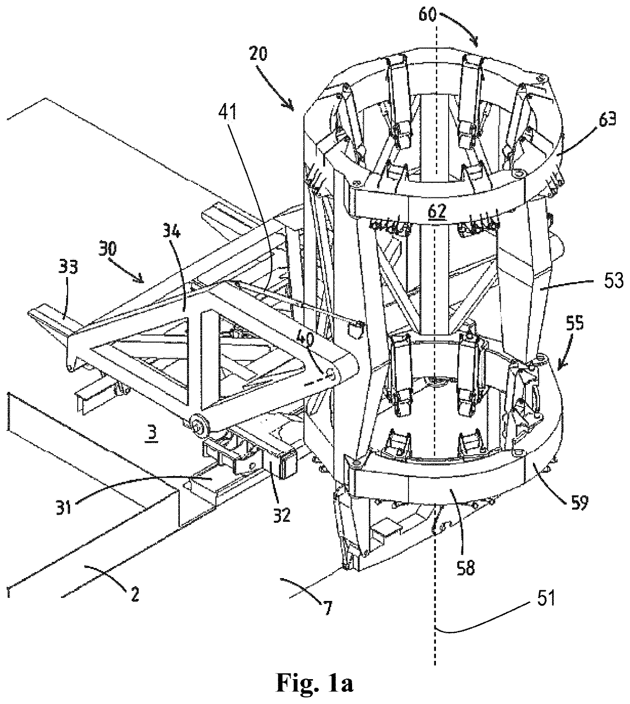
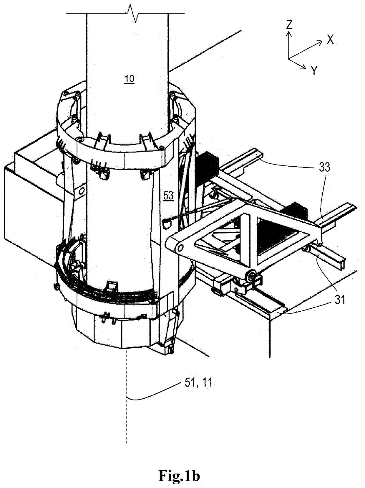
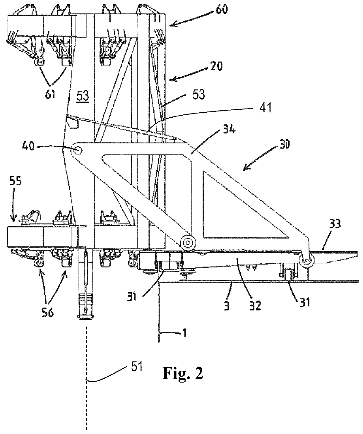
[0200]In the figures a vessel is partly indicated with reference numeral 1.

[0201]In this example, the vessel is equipped with a crane 2 configured to lift a monopile 10 for an offshore wind turbine.

[0202]For example, the vessel 1 has a deck 3 on which one or more monopiles 10 are stored in horizontal orientation, e.g. transverse to a longitudinal axis of the vessel.

[0203]The vessel 1 is equipped with an pile upending and holding system 20 according to the invention, that is configured to be mounted on the vessel 1, e.g. on a deck 3 thereof, e.g. on a deck thereof and in close proximity to the crane 2.

[0204]The system 20 is used in conjunction with the crane 2, and a pile driving device 100, for installation of the monopile 10 into the seabed. A wind turbine, e.g. with a transition piece in between, is then placed on the monopile.

[0205]Generally the system 20 comprises a support assembly 30 that is configured to be mounted on the vessel 1, e.g. on a deck 3 of the vessel, and a pile h...


PUM


Abstract

A pile upending and holding system includes a support assembly configured to be mounted on the vessel and to provide compensation for wave-induced motion of the vessel to maintain a predetermined X-Y location of the pile holder independent of said motion, and a pile holder mounted on the support assembly to be tillable about a substantially horizontal tilt axis. The pile holder includes a lower ring and an upper ring, and a pile holder frame supporting the lower ring and upper ring, the upper ring longitudinally spaced from the lower ring. Each of the rings include pile engaging devices distributed about the circumference thereof, each pile engaging device being adapted to engage an exterior of the pile extending through the lower and upper ring. Each of the lower ring and upper ring includes a ring base fixed to the pile holder frame and one or more movable jaws, movable between a closed position for holding and guiding the pile and an opened position for entry of the pile. The pile holder is provided, below the lower ring thereof, with a pile foot end support for engaging a longitudinal end of the pile to limit longitudinal movement thereof.

Description

FIELD OF THE INVENTION[0001]The invention relates to a pile upending and holding system configured to be mounted on a vessel, e.g. for installation of a pile, e.g. a monopile, adapted to support an offshore wind turbine. The invention further relates to a vessel comprising such a system and a method for using the system.BACKGROUND OF THE INVENTION[0002]Installation of an offshore wind turbine comprises the step of installing the foundation, often in the form of a pile, e.g. a monopile, of the offshore wind turbine. A pile is installed by driving the pile into the seabed after which the upper part of the wind turbine is arranged on top of the pile. In known methods, the pile is initially supported on a jack-up vessel in a horizontal orientation. In a typical operational sequence to install the pile, the pile is firstly upended, i.e. is pivoted in an upright position. Subsequently, the pile is lowered to the seabed at the pile installation location. Finally the pile, more in particula...

Claims


Application Information

Patent Timeline
IPC IPC(8): E02D13/04E02D7/00E02D15/08B63B35/00B63B27/10
CPCE02D13/04E02D7/00E02D15/08B63B35/00B63B27/10F03D13/25B63B75/00E02D27/525B63B27/16B66C23/52E02B2017/0091E02B17/06E02B17/04E02B2017/0039E02B2017/0065
Inventor VEHMEIJER, TERENCE WILLEM AUGUSTWETERINGS, HENDRIKUS JACOBUSVAN RUYVEN, STEFAN CORNELISBOELENS, RENE CORNEILLE LOSIRIAI
Owner ITREC BV
Why Eureka
Try Eureka