Sealing Assembly in a Thrust Bearing King Pin Application

a technology of sealing assembly and king pin, which is applied in the direction of rolling bearings, steering parts, road vehicles, etc., can solve the problems of premature failure of the bearing used, inability to attend to life-long lubrication, and inability to seal the assembly in the application of king pin, so as to avoid damage to the delicate lips, preserve grease, and efficient and compact

a technology of sealing assembly and king pin, which is applied in the direction of rolling bearings, steering parts, road vehicles, etc., can solve the problems of premature failure of the bearing used, inability to attend to life-long lubrication, and inability to seal the assembly in the application of king pin, so as to avoid damage to the delicate lips, preserve grease, and efficient and compact

US20130051721A1Active Publication Date: 2013-02-28NRB BEARINGS

Image

  • Sealing Assembly in a Thrust Bearing King Pin Application
  • Sealing Assembly in a Thrust Bearing King Pin Application
  • Sealing Assembly in a Thrust Bearing King Pin Application

Examples


Embodiment Construction

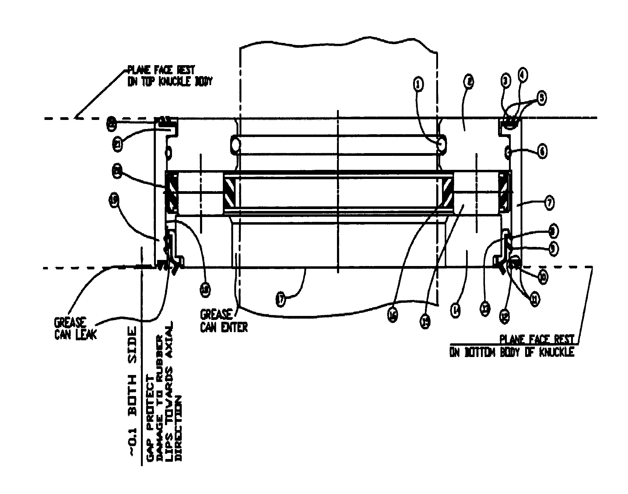
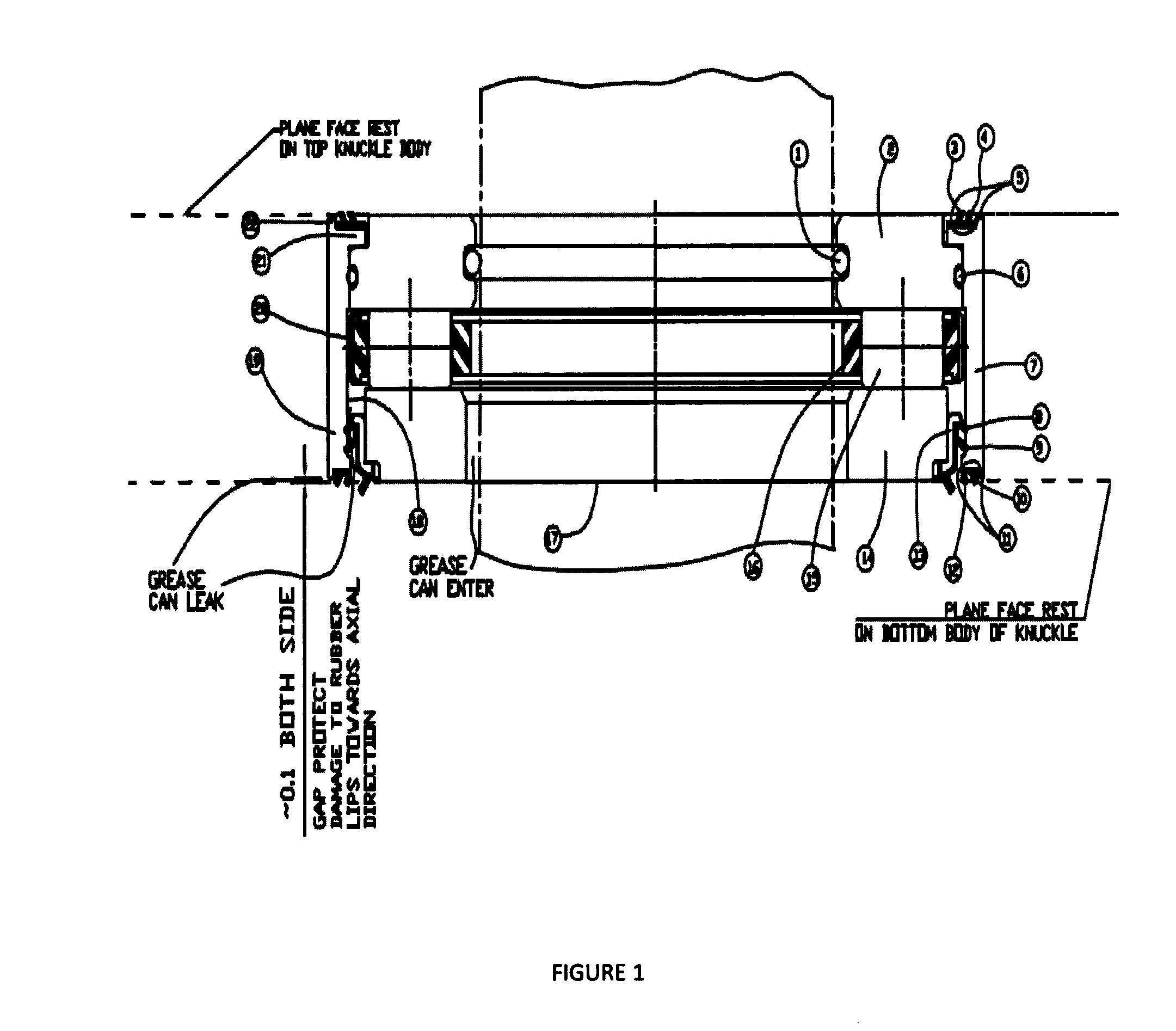
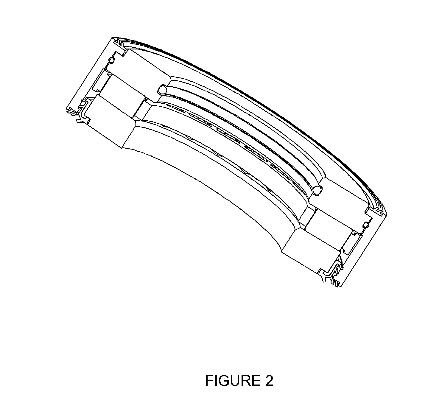
[0014]With reference to FIGS. 1, 2, and 3, the bearing assembly contains external envelop [07] made up of special alloy stainless steel material and cylindrical machined parts with close rim at both end to hold seals, washers and rollers. In the bearing assembly, external envelop [07] acts as external portion of the bearing and holds rolling elements, cage, top washer, bottom washer and guides those during oscillation or rotation. It also acts as means to keep integer all part together. The envelop [07] contains flat face [19, 21] to provide room for rubber lip holding. The extreme end [11, 22] envelops the delicate lip of rubber seals and protects them from the external factors. The portion of the envelop ID [20] guides roller cage assembly [15, 16] and create sealing at [08, 09]. As per one of the preferred embodiment of present invention the washer portion [02, 14] prevented with contamination by rubber seal lips [03, 04, 10, and 12]. The portion [22] is closely guided by top and...


PUM


Abstract

A thrust bearing with a improved sealing assembly includes external envelop such as with close rim at both ends having flat face to provide room for rubber lip folding and sealing such as double lip seal with two axial lips. The axis of rubber lips are inclined with relevant mating part. The extreme ends of the envelop envelops the delicate lip of rubber seals. The portion of the envelop ID [20] is put in a manner to guides roller cage assembly and create sealing at [08, 09]. The bearing external envelop is used as stiffener for body of double lip seal. The shape and design of the external machine cover face accommodate lips of seals, protect seals lips and hold the bearing together.

Description

FIELD OF THE INVENTION[0001]The present invention generally relates to a sealing assembly in a thrust bearing king pin application and thrust load application. The present invention particularly relates to a sealing assembly in a thrust cylindrical roller bearing assembly comprising of a sealing device for inhibiting / preventing the entry of pollution in the bearing and allow leakage of lubrication to mating parts of king pin knuckle joints.[0002]The present invention more particularly relates to king pin application / thrust load application cylindrical thrust bearing assembly comprising of a double lip seal on radial direction and on faces having stainless steel machined sleeve stiffener acting as an envelop to the bearing assembly. The present invention provides a life long lubrication. The new concept is made out of machined part and adds a new function of double sealing at top and bottom side to the knuckle face. By adding a additional sealing friction gets deduced.DESCRIPTION OF ...

Claims


Application Information

Patent Timeline
28 Feb 2013
Publication
US20130051721A1
IPC
F16C33/76; F16C19/30
CPC
B62D7/18; F16C33/761; F16C19/30; F16C2326/24
Inventors
SALUNKE, SURESH T.