Printer

a printing machine and printing plate technology, applied in printing, metal working equipment, other printing equipment, etc., can solve the problems of reducing the operator may mistakely touch the cutting blade, and so as to increase the safety of the operator, improve the positioning accuracy of the blade, and increase the rigidity of the supporting structure of the blad

Active Publication Date: 2013-02-28
BROTHER KOGYO KK
View PDF5 Cites 5 Cited by
  • Summary
  • Abstract
  • Description
  • Claims
  • Application Information

AI Technical Summary

Benefits of technology

[0008]It is therefore an object of the present disclosure to provide a printer capable of ensuring the safety of the operator with respect to the blade, without rendering a decrease in rigidity or positioning accuracy, even when the opening / closing part is open.
[0011]Further, according to the present disclosure, a fixed blade cover capable of covering the blade edge of the fixed blade in conjunction with the open state and closed state of the opening / closing part is provided. At that time, the fixed blade cover is integrally provided to the print head which moves toward and away from the feeding roller in conjunction with the open state and closed state of the opening / closing part, making it possible to perform the opening / closing operation of the opening / closing part and the movement of the fixed blade cover and the print head together in coordination.
[0013]As described above, in this present disclosure, it is possible to not inhibit use of the fixed blade when the opening / closing part is closed and the printing operation is performed, and cover and not expose the blade edge of the fixed blade when the opening / closing part is open. Accordingly, it is possible to increase the safety of the operator when the opening / closing part is open.
[0014]Further, at this time, because the structure is designed so that the fixed blade cover moves while the fixed blade is fixed as is as described above, the rigidity of the support structure of the blade can be increased and the positioning accuracy of the blade can be improved compared to the prior art in which the blade moves.

Problems solved by technology

At this time, the internal structure of the housing is exposed by opening the opening / closing part, resulting in the possibility that the operator may mistakenly touch the cutting blade during the above described work.
Nevertheless, in the above described prior art, because the structure is designed so that the blade moves in association with the opening and closing of the opening / closing part as described above, the problem arises that the rigidity of the support structure of the blade decreases, decreasing the positioning accuracy of the blade.

Method used


Image

  • Printer
  • Printer
  • Printer

Examples


Embodiment Construction

[0027]The following describes one embodiment of the present disclosure with reference to accompanying drawings.

General Configuration of Printer

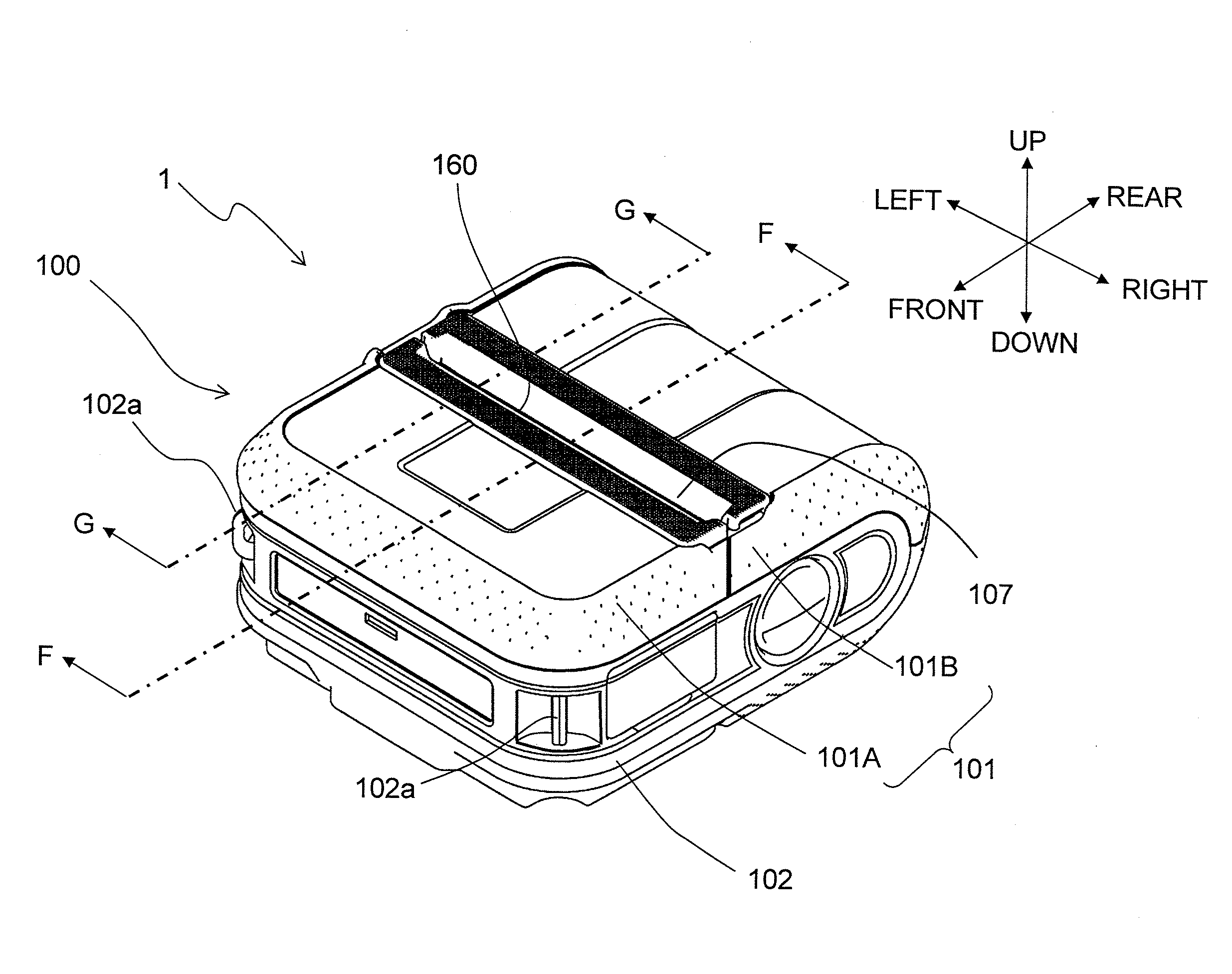
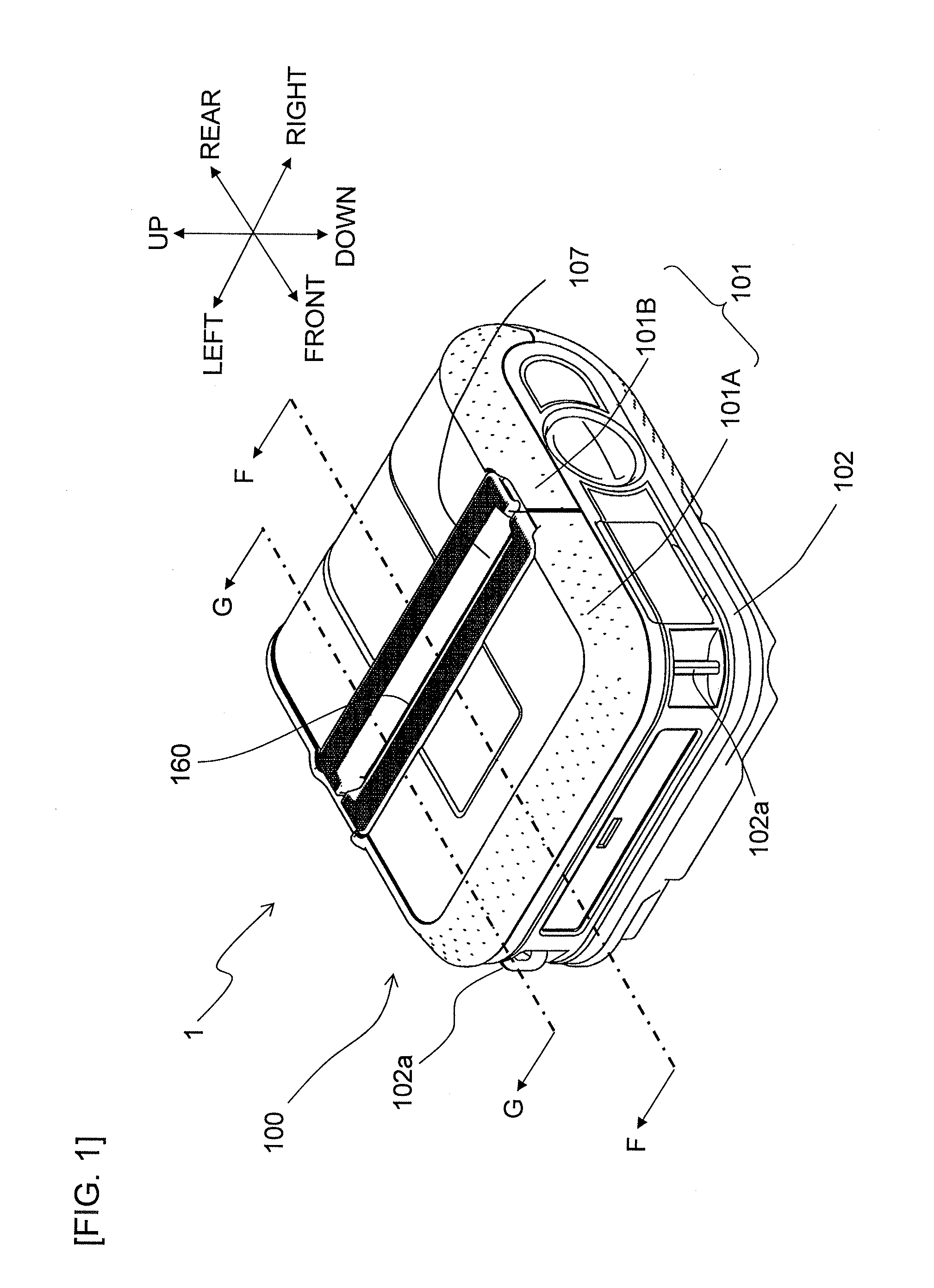
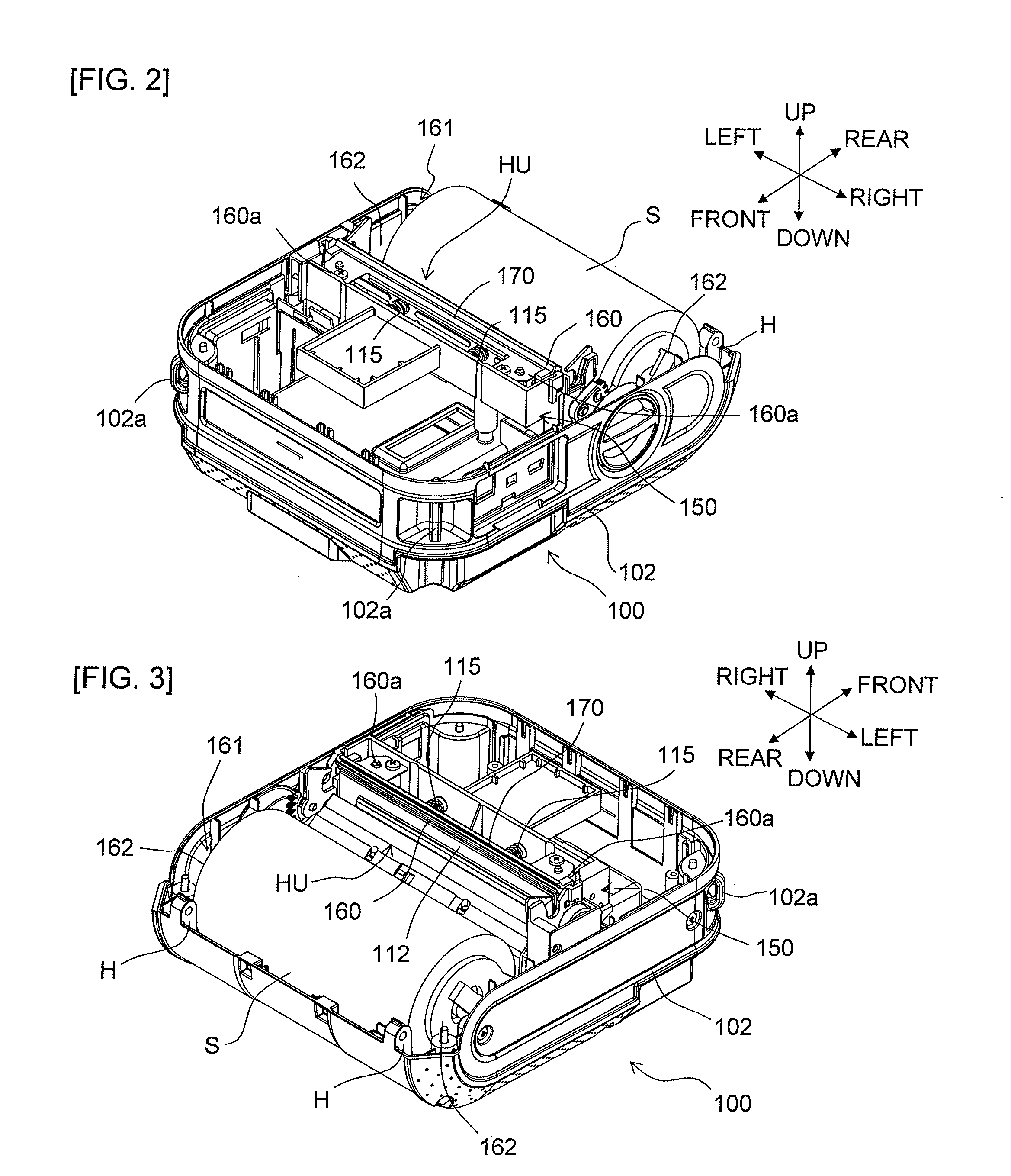
[0028]The following describes the overall configuration of a printer 1, which is one embodiment of the present disclosure, using FIG. 1 to FIG. 4. In the description, the lower right direction, upper left direction, upper right direction, lower left direction, upper direction, and lower direction in FIG. 1 are defined as the right, left, rear, front, up, and down directions, respectively (refer to the arrows of each figure).

[0029]The printer 1 prints print data received from an external device (not shown) such as a PC terminal, cellular telephone, or the like onto a rolled paper S, for example. This printer 1 can be driven using a battery (not shown) as a power source.

[0030]The printer 1 comprises a substantially box-shaped printer housing 100 which constitutes the printer contour and is made of a resin material, for example. This printer hou...


PUM


Abstract

The disclosure discloses a printer comprising: a fixed part and an opening / closing part; a feeding roller configured to feed the print-receiving medium; a print head; a discharging exit configured to discharge the print-receiving medium; a fixed blade fixed to the fixed part so as to follow along an edge part of the discharging exit; a fixed blade cover; and a support device configured to support in a relatively displaceable manner the print head and the fixed blade cover, forming a first state wherein the fixed blade cover covers the blade edge of the fixed blade and the print head separates from the feeding roller when the opening / closing part changes to an open state, and a second state wherein the fixed blade cover does not cover the blade edge of the fixed blade and the print head presses against the feeding roller when the opening / closing part changes to a closed state.

Description

CROSS-REFERENCE TO RELATED APPLICATION[0001]The present application claims priority from Japanese Patent Application No. 2011-187868, which was filed on Aug. 30, 2011, the disclosure of which is incorporated herein by reference in its entirety.BACKGROUND[0002]1. Field[0003]The present disclosure relates to a printer configured to perform desired printing on a print-receiving medium.[0004]2. Description of the Related Art[0005]There are known printers that perform desired printing on and subsequently cut a print-receiving medium to generate a printed matter. In such a printer are provided a storage part, a feeding roller (paper feeding roller), and print head. The print-receiving medium (rolled paper) supplied from a roll stored in the storage part is fed by the feeding roller, and desired printing is performed by the print head on the that fed print-receiving medium. The print-receiving medium after printing is discharged from a discharging exit of the housing to the outside. An ope...

Claims


Application Information

Patent Timeline
Patent Type & Authority Applications(United States)
IPC IPC(8): B41J11/70
CPCB26D7/22B26D1/025B41J11/70B41J15/042
Inventor YOKOE, ASAMI
Owner BROTHER KOGYO KK
Why Eureka
Try Eureka