Device and method for replacing mitral valve

a technology of mitral valve and valve body, which is applied in the field of prosthetic mitral valve, can solve the problems of heart valves being rendered less effective, serious cardiovascular damage or death, and surgery being prone to many complications, so as to prevent the movement of the mitral valve assembly and reduce the stress on the leaflets

Inactive Publication Date: 2013-02-28
EDWARDS LIFESCIENCES CORP
View PDF4 Cites 195 Cited by
  • Summary
  • Abstract
  • Description
  • Claims
  • Application Information

AI Technical Summary

Benefits of technology

[0013]In still other embodiments, when positioned above the annulus, prongs or other attachment mechanisms on an outer surface of the stent may be used to resist upward movement of the mitral valve assembly. Alternatively (or in addition), a tether or other anchoring member can be attached to the stent at one end and secured to a portion of the heart at another end in order to prevent movement of the mitral valve assembly after implantation. A tether may also be used to decrease the stress on the leaflets of the replacement valve and / or to re-shape the left ventricle.

Problems solved by technology

These heart valves can be rendered less effective by congenital, inflammatory or infectious conditions.
Such damage to the valves can result in serious cardiovascular compromise or death.
For many years the definitive treatment for such disorders was the surgical repair or replacement of the valve during open heart surgery, but such surgeries are prone to many complications.
While procedures for the aortic valve are well-developed, such procedures are not necessarily applicable to the mitral valve.
However, a significant percentage (i.e., about 33%) of patients still receive open-heart surgical mitral valve replacements due to calcium, stenosis, or anatomical limitations.
However, for mitral valve replacement, few less-invasive options are available.
There are approximately 60,000 mitral valve replacements (MVR) each year and it is estimated that another 60,000 patients should receive MVR, but are denied the surgical procedure due to risks associated with the patient's age or other factors.

Method used


Image

  • Device and method for replacing mitral valve
  • Device and method for replacing mitral valve
  • Device and method for replacing mitral valve

Examples


Embodiment Construction

[0033]As used herein, the singular forms “a,”“an,” and “the” refer to one or more than one, unless the context clearly dictates otherwise.

[0034]As used herein, the term “includes” means “comprises.” For example, a device that includes or comprises A and B contains A and B but can optionally contain C or other components other than A and B. A device that includes or comprises A or B may contain A or B or A and B, and optionally one or more other components such as C.

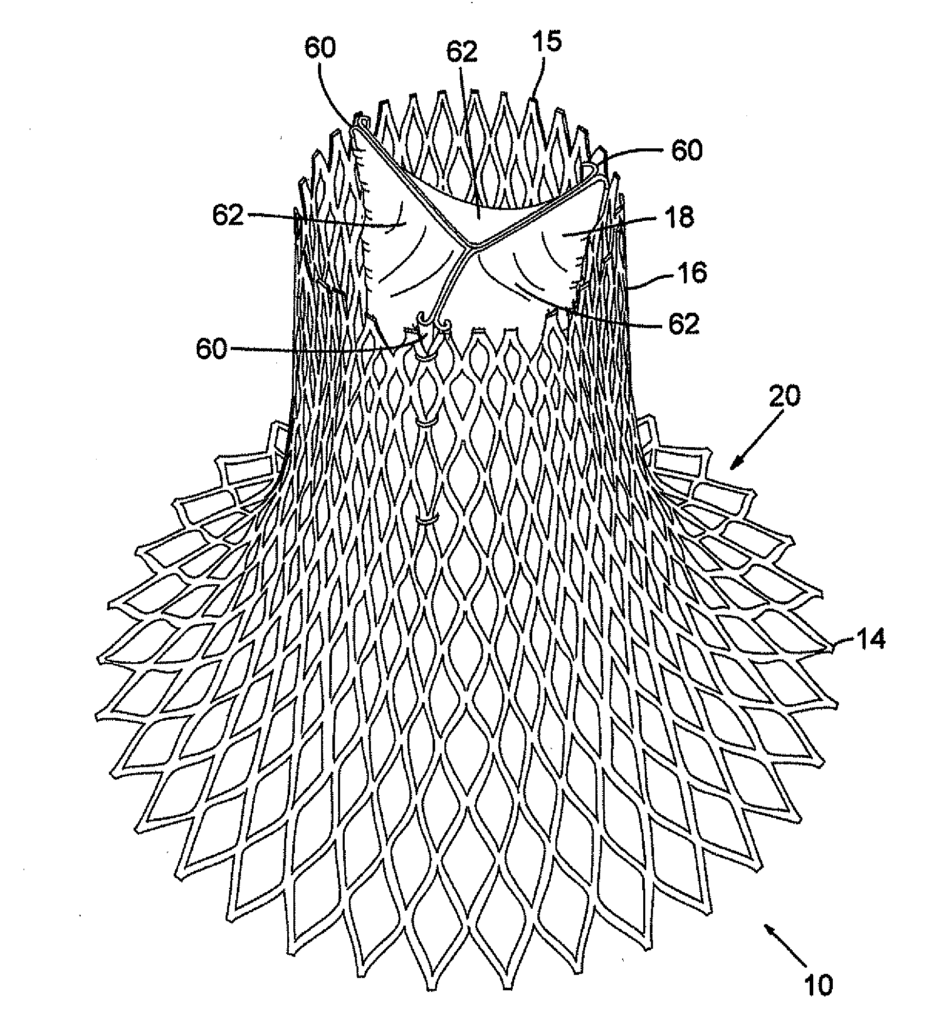
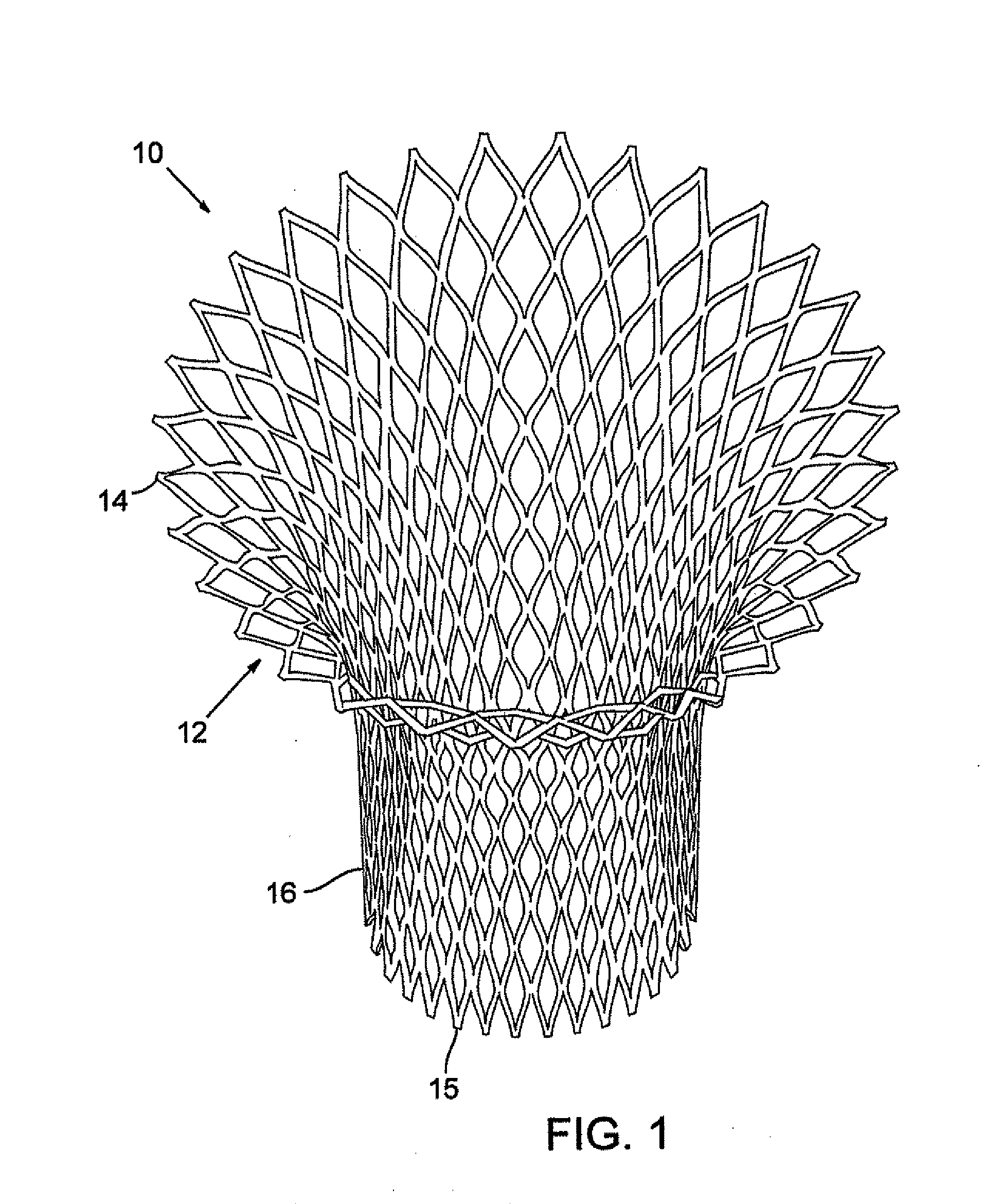
[0035]FIG. 1 is a perspective view of a stent 10 configured for placement in a native mitral valve. The stent in this embodiment includes an upper portion 12 having an enlarged or flared end 14 that tapers to a lower portion 16 having a reduced diameter. The stent generally has a bell shape or a truncated conical shape, but other shapes can be used. The stent 10 can have a continuous taper from the flared end 14 to the lower end 15. As described below, at least the upper portion desirably tapers in a direction from the up...


PUM


Abstract

A prosthetic mitral valve assembly is disclosed. The assembly comprises a radially-expandable stent including a lower portion sized for deployment between leaflets of a native mitral valve and an upper portion having a flared end. The upper portion is sized for deployment within the annulus of the mitral valve and the flared end is configured to extend above the annulus. The stent is formed with a substantially D-shape cross-section for conforming to the native mitral valve. The D-shape cross-section includes a substantially straight portion for extending along an anterior side of the native mitral valve and a substantially curved portion for extending along a posterior side of the native mitral valve. The assembly further includes a valve portion formed of pericardial tissue and mounted within an interior portion of the stent for occluding blood flow in one direction.

Description

RELATED APPLICATIONS[0001]This application is a divisional of U.S. patent application Ser. No. 12 / 113,418, filed May 1, 2008, the disclosure of which is incorporated by reference.FIELD[0002]The present disclosure concerns a prosthetic mitral heart valve and a method for implanting such a heart valve.BACKGROUND[0003]Prosthetic cardiac valves have been used for many years to treat cardiac valvular disorders. The native heart valves (such as the aortic, pulmonary and mitral valves) serve critical functions in assuring the forward flow of an adequate supply of blood through the cardiovascular system. These heart valves can be rendered less effective by congenital, inflammatory or infectious conditions. Such damage to the valves can result in serious cardiovascular compromise or death. For many years the definitive treatment for such disorders was the surgical repair or replacement of the valve during open heart surgery, but such surgeries are prone to many complications. More recently a...

Claims


Application Information

Patent Timeline
Patent Type & Authority Applications(United States)
IPC IPC(8): A61F2/24
CPCA61B17/0401A61B2017/00243A61B2017/0417A61B2017/0496A61F2/2418A61F2230/0078A61F2002/8486A61F2220/0008A61F2220/0016A61F2230/0054A61F2/2457A61L27/50A61L2430/20A61F2/2436A61F2250/0039A61F2210/0014A61F2230/0067A61L27/3625A61F2/2454A61F2/2427A61F2/90
Inventor ROWE, STANTON J.CHAU, MARKNGUYEN, SON V.
Owner EDWARDS LIFESCIENCES CORP
Why Eureka
Try Eureka