Middle ear prosthesis having discrete projections for purposes of ossicular attachment

a technology of ossicular attachment and projection, which is applied in the field of middle ear prosthesis, can solve the problems of not effectively transmitting ossicular motion to the fluids of the inner ear, hearing loss, and often dysfunction, and achieves the effects of reducing the chance of necrosis, broad contact, and minimizing disturbance to the underlying mucosa and blood vessels

Inactive Publication Date: 2013-02-28
SCHEURER MARK MATTHEW
View PDF5 Cites 8 Cited by
  • Summary
  • Abstract
  • Description
  • Claims
  • Application Information

AI Technical Summary

Benefits of technology

The invention proposes a new way to attach an ossicular implant to an ossicle without causing damage to the surrounding tissues. This reduces the risk of complications like inflammation and nerve injury during surgeries. By avoiding direct contact between the device and the host bone, it also decreases the likelihood of rejection or migration after surgery. Overall, this innovative approach improves the reliability and safety of ossicular replacement procedures.

Problems solved by technology

The technical problem addressed in this patent is how to design an ossicular prosthesis that does not compress upon the adjacent bone or vascular structures, thereby reducing the risk of complications such as bone erosion, implantation failures, and sensorineural losses.

Method used


Image

  • Middle ear prosthesis having discrete projections for purposes of ossicular attachment
  • Middle ear prosthesis having discrete projections for purposes of ossicular attachment
  • Middle ear prosthesis having discrete projections for purposes of ossicular attachment

Examples


Embodiment Construction

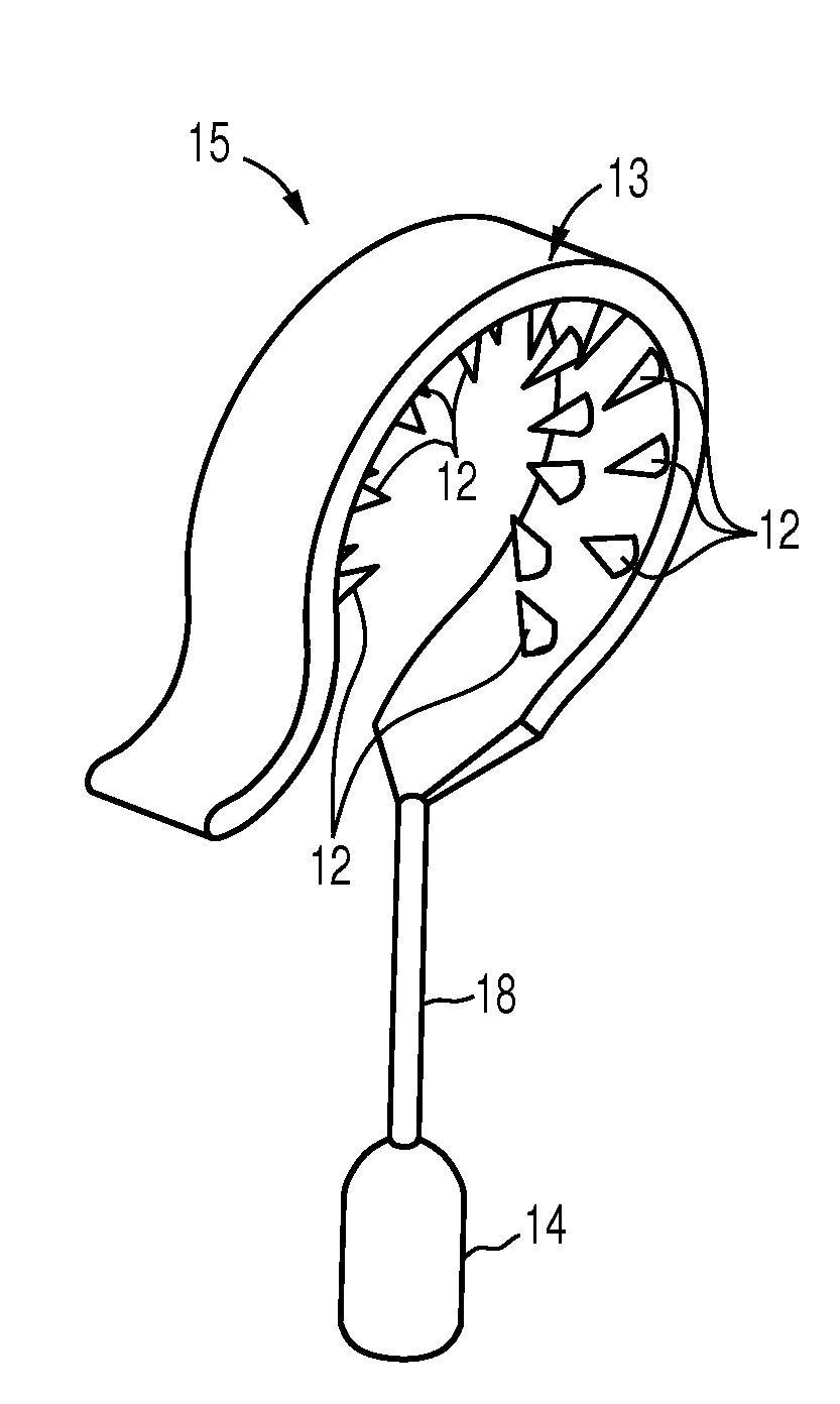
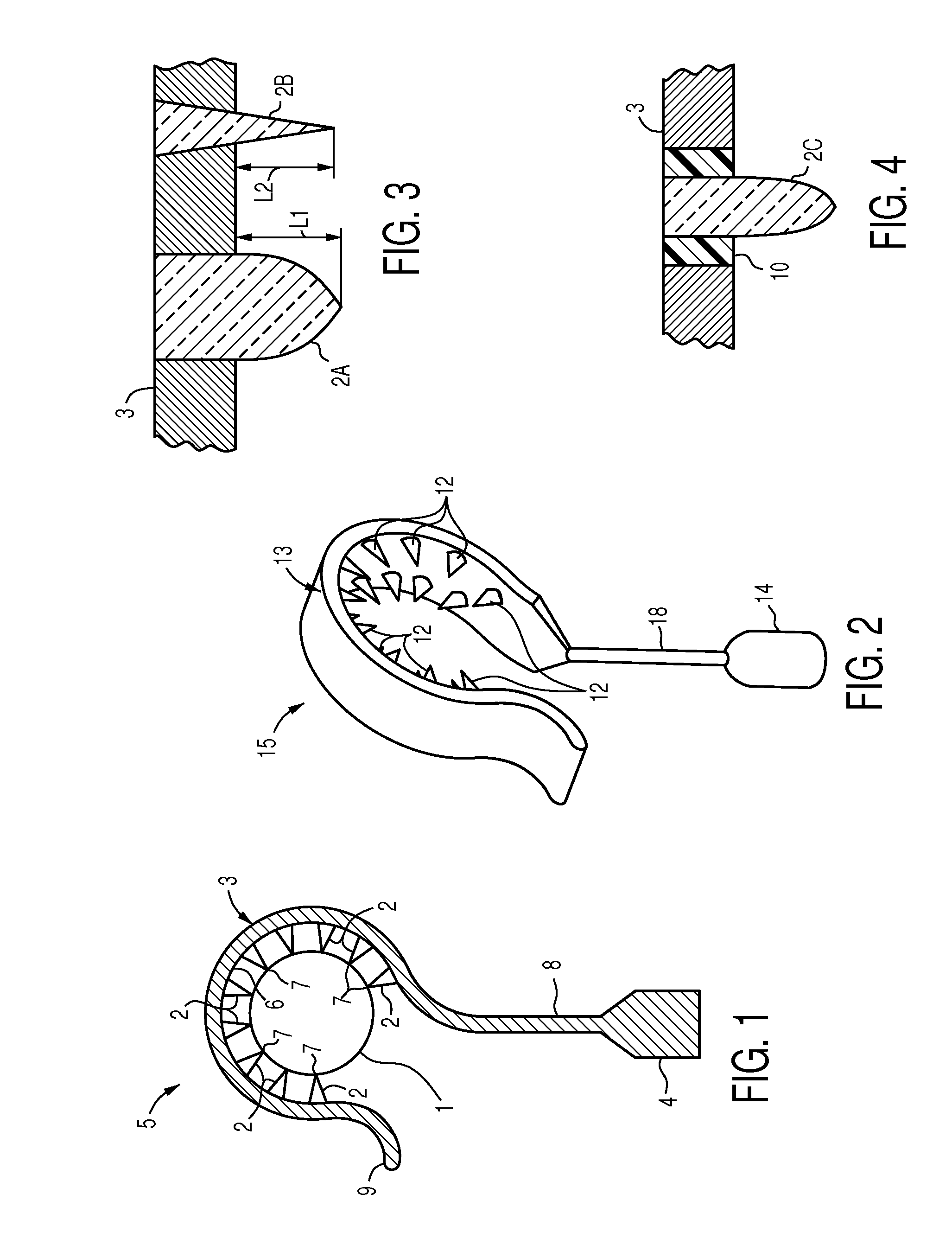
[0022]FIG. 1 shows a middle ear prosthesis such as a stapes prosthesis 5 comprising a loop 3 which is formed as a partial circle of at least one hundred eighty degrees, or as shown, three hundred to three hundred thirty degrees, for encircling an ossicle such as an incus 1 (seen in cross section in FIG. 1). It would of course be possible to arrange the loop 3 as a full circle, by adding an element which closes the gap which exists when the loop 3 forms a partial circle as depicted and a suitable fastener for retaining the added element to the loop 3 (this option is not shown). The loop 3 bears a linear array of projections or spikes 2, which may for example be arrayed as a row of spikes 2, which project inwardly from the inner surface 6 of the loop 3, and which make contact with the underlying incus 1. The terms projection and spike, both in the singular and in the plural, will be used interchangeably herein. Inwardly signifies towards the center of the circle which would exist if t...


PUM

PropertyMeasurementUnit
Angleaaaaaaaaaa
Lengthaaaaaaaaaa
Shapeaaaaaaaaaa

Abstract

A middle ear ossicle prosthesis in which the component for ossicular attachment comprises a surface bearing a plurality of discrete projections facing the ossicle to which it is attached which minimize total contact between the prosthesis and the ossicle. The prosthesis may comprise a loop forming a partial circle for encircling an ossicle, a piston for transmitting vibrations from the loop to the inner ear, and a rod solidly connecting the loop to the piston. The loop may have an upwardly turned end to facilitate placement of the loop over the ossicle. The projections may be provided in one row, two rows, or may be otherwise arrayed, and may be dissimilar from one another in configuration and dimensions.

Description


Claims


Application Information

Patent Timeline
Owner SCHEURER MARK MATTHEW
Why Eureka
Try Eureka