
Cap Sanitizer and Method of Use Thereof

a technology of sanitizer and cap, which is applied in the direction of cleaning process and apparatus, cleaning using liquids, containers preventing decay, etc., can solve the problems of contaminating the solution being dispensed, and the device does not prevent the leakage of sanitizing materials, etc., and achieves the effect of cleaning the toothbrush

Inactive Publication Date: 2013-03-14
WOOLERY PAMELA
View PDF3 Cites 8 Cited by
  • Summary
  • Abstract
  • Description
  • Claims
  • Application Information

AI Technical Summary

Benefits of technology

The present invention provides a cap sanitizer for dispensing bottles or devices. The cap has a continuous sponge ring soaked in antibacterial solution, with o-rings to prevent solution from leaking. Another embodiment has a sponge-less inner tip portion as a reservoir for antibacterial solution, which is slowly channeled to the sponge ring via a perforated separating film. The technical effects of this invention are that it provides a convenient way to sanitize dispensing elements, reducing the risk of bacterial contamination and improving food safety.

Problems solved by technology

However, this device teaches utilizing a separate wick as the channeling means between the biocide reservoir and the pad; further, the pad contacts the tip of the dispenser which could lead to contamination of the solution being dispensed.
Lastly, this device does not prevent leaking of the sanitizing material from the dispenser cap either when removed or in place.
However, the reservoir, the perforated separator, and the sponge material are not all contained with the inner cap portion.
Moreover, the device contains storage only for the product being dispensed and does not contain a separate solution for applying to the tip of the dispenser for cleaning and / or sanitizing.

Method used


Image

  • Cap Sanitizer and Method of Use Thereof
  • Cap Sanitizer and Method of Use Thereof
  • Cap Sanitizer and Method of Use Thereof

Examples


Embodiment Construction

[0044]In describing the preferred and selected alternate embodiments of the present invention, as illustrated in FIGS. 1-4B, specific terminology is employed for the sake of clarity. The invention, however, is not intended to be limited to the specific terminology so selected, and it is to be understood that each specific element includes all technical equivalents that operate in a similar manner to accomplish similar functions.

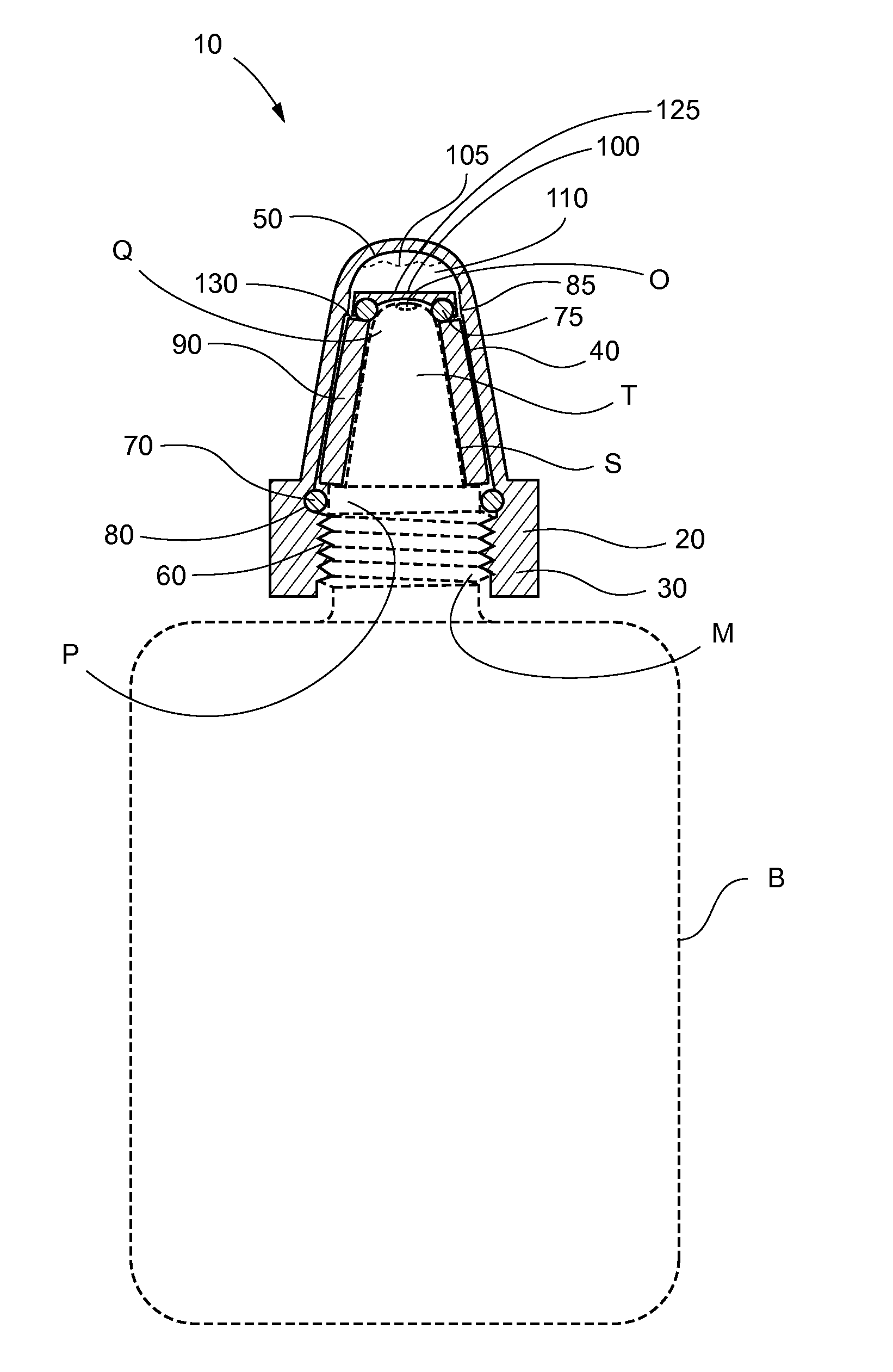
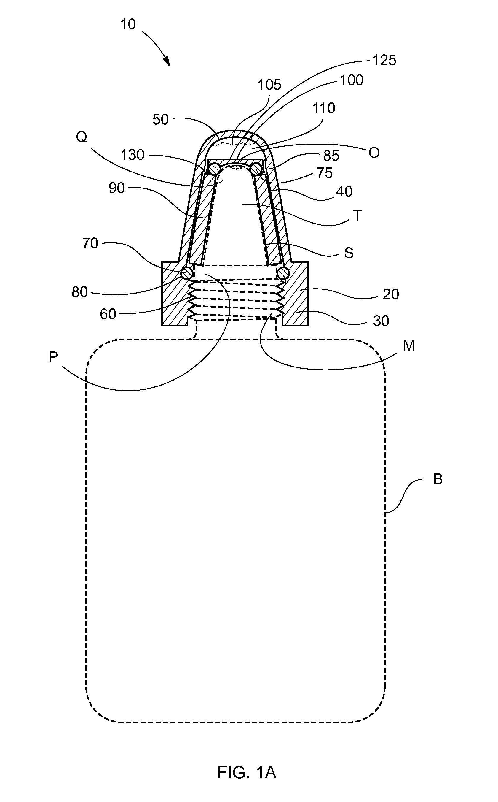
[0045]Referring now to FIGS. 1A-1B, the present invention in a preferred embodiment is cap sanitizer 10 comprising cap 20, wherein cap 20 comprises bottom 30, middle 40 and top 50. Within cap 20 is disposed an applying surface, such as, for exemplary purposes only, sponge 90, wherein sponge 90 comprises top boundary 130. Further disposed within cap 20 are perforated membrane 100, cavity 105 and sanitizing solution 110, wherein perforated membrane 100 comprises apertures 120, and wherein cavity 105 contains sanitizing solution 110. Bottom 30 comprises internal...


PUM


Abstract

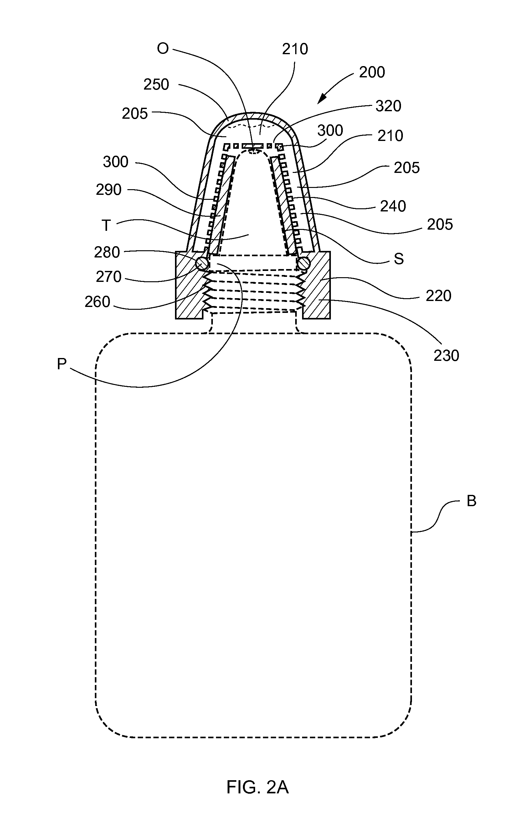
A cap sanitizer with an anti-bacterial sponge therein for sanitizing a dispenser bottle tip or other similar device. The inner side portions of the cap are lined with a continuous sponge (or absorbent foam) ring soaked with antibacterial solution. An o-ring is disposed below the sponge to prevent solution from leaking from the dispenser bottle when the cap is in place. A cavity within the dispenser cap serves as a reservoir for the antibacterial solution, which is slowly channeled to the sponge ring via a perforated separating film. Alternatively, the reservoir may be disposed between the sponge and the sides of the dispenser cap sanitizer, with a perforated separating film between the sponge and the antibacterial solution. Solution from the reservoir is channeled through the perforated separating film into the sponge. In an alternative, a sanitizer cap for a toothbrush is provided having stiff fibers extending through the perforated membrane.

Description

CROSS-REFERENCE TO RELATED APPLICATIONS[0001]NoneFEDERALLY SPONSORED RESEARCH OR DEVELOPMENT[0002]NonePARTIES TO A JOINT RESEARCH AGREEMENT[0003]NoneREFERENCE TO A SEQUENCE LISTING[0004]NoneBACKGROUND OF THE INVENTION[0005]1. Technical Field of the Invention[0006]The present invention relates generally to apparatuses for sanitizing implements, and more specifically to a sanitizing cap for automatically sanitizing the tip of dispenser bottles after each use.[0007]2. Description of Related Art[0008]Various liquid chemical ingredients are dispensed via dispenser bottles that are utilized for multiple applications.[0009]One previous device comprises a disinfectant cap for a sterile liquid dispenser. The cap is adapted with a biocide-containing pad that is fixed to the upper inner cap surface, and may extend partly or completely down the inner cap surface. Consequently, when the cap is secured to the liquid dispenser, the pad either partly or completely covers the dispensing element ther...

Claims


Application Information

Patent Timeline
Patent Type & Authority Applications(United States)
IPC IPC(8): B08B1/00B08B3/00
CPCB08B1/00B65D51/28B65D81/28B08B3/08B08B1/14
Inventor WOOLERY, PAMELA
Owner WOOLERY PAMELA
Learn More