Control motion hinge with torsion spring

a technology of motion closure and control mechanism, which is applied in the field of hinges, can solve the problems of deformation of the door, hinge, latch/lock and frame over time, noise to the ear and forceful impact, and impaired main elements of the hinge, lock and door elements

Inactive Publication Date: 2011-11-10
IRWIN ROBERT F
View PDF8 Cites 5 Cited by
  • Summary
  • Abstract
  • Description
  • Claims
  • Application Information

AI Technical Summary

Benefits of technology

[0006]Briefly described, in a preferred embodiment, the present apparatus overcomes the above-mentioned disadvantage, and meets the recognized need for such an apparatus by providing a control motion hinge comprising, in general, a first leaf hinge to secure a first pin, a second hinge to secure a first pin, a link positioned between the first and second leaf hinge, a flat spring wrapped around the knuckle of the first and second leaf hinge, activates a closure cycle of the control motion hinge pulling the door closed.

Problems solved by technology

Moreover, such door closing systems apply a non-uniform force to the upper portion of the door disadvantageously resulting in a force offset from the rotational axis of the hinge assembly, thus deforming the door, hinge, latch / lock and frame over time.
When a door is closed with the assistance of such door closing systems, it is typically forced to move in its closing direction rapidly, causing a noise to the ear and forceful impact, wherein the main elements the hinge, lock and door elements are impaired over time due to such force.

Method used


Image

  • Control motion hinge with torsion spring
  • Control motion hinge with torsion spring
  • Control motion hinge with torsion spring

Examples


Embodiment Construction

[0040]In describing the preferred and alternate embodiments of the present invention, as illustrated in FIGS. 1-7 specific terminology is employed for the sake of clarity. The present invention, however, is not intended to be limited to the specific terminology so selected, and it is to be understood that each specific element includes all technical equivalents that operate in a similar manner to accomplish similar functions.

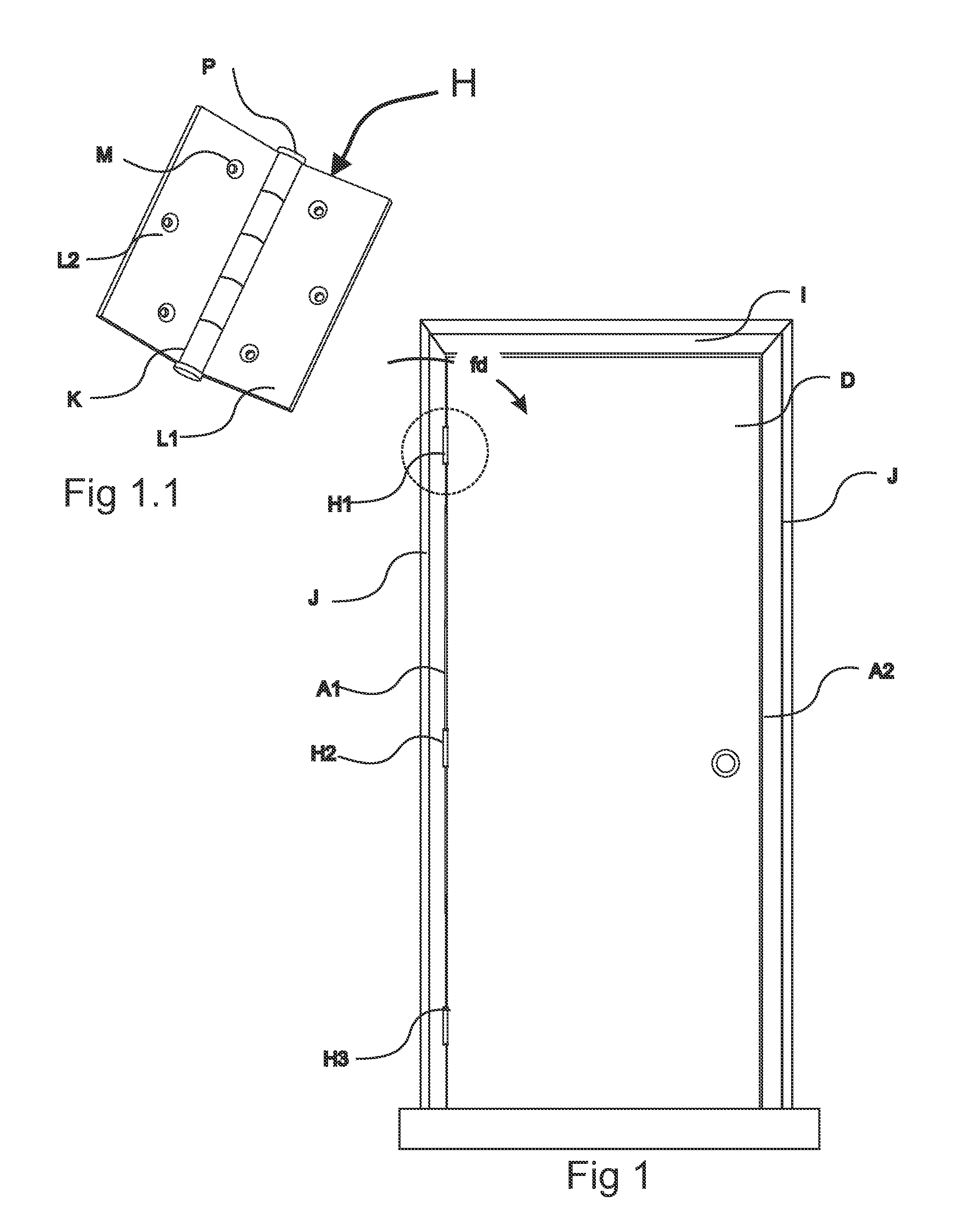
[0041]Referring now to FIGS. 1 and 1.1, there is depicted a prior art door D, door jam J, door header I and three hinge assembly H1, H2, and H3. The door D, which swings inward, toward the viewer as depicted in FIG. 1, fits closely to jam J at both its hinge edge A1 and its opposite or latch edge A2. Door A may be configured to swing inward or outward by switching the configuration of hinge assembly H1, H2, and H3. It should be noted, also, that no hinge is exposed to view along the hinge edge A1 when the door is closed as viewed from the other side of door D.

[0...


PUM


Abstract

A control motion hinge, comprising a first leaf hinge with three knuckles to secure a first pin, wherein the two outer knuckles have roller knuckles, a link having a two knuckles on a first end to interlock with the first leaf hinge and a single knuckle on a second end, a second leaf hinge with two knuckles to secure a second pin when interlocked with the second end of the link, wherein the two knuckles of the second leaf hinge have a roller path for engaging the roller of the first leaf hinge, wherein such rollers traverse the roller path, a first spring device positioned between said first leaf hinge and said link to apply a force therebetween, and thus softly closing the door reducing the sound of closure during the final approach of the door.

Description

PRIORITY CLAIM TO RELATED US APPLICATIONS[0001]To the full extent permitted by law, the present U.S. Non-provisional patent application, is a Continuation-in-Part of, and hereby claims priority to and the full benefit of U.S. Non-provisional application entitled “Control Motion Hinge,” having assigned Ser. No. 12 / 775,302, filed on May 6, 2010, incorporated herein by reference in its entirety.FIELD OF THE INVENTION[0002]The present invention relates generally to hinge and more specifically to a door hinge with a motion closure system for soft closure of the door.BACKGROUND OF THE INVENTION[0003]The conventional door hinge or butt-hinge is composed of two leaves each engages with the other by means of a pivot pin and interlocking sleeve, knuckle or pintle. One leaf is fixed on the door edge and the other is fixed on the door frame. One or more hinges are used to pivot the door when opening or closing the door. For automatically closure of the door with a conventional hinge, a hydrauli...

Claims


Application Information

Patent Timeline
Patent Type & Authority Applications(United States)
IPC IPC(8): E05D11/04E05D11/00E05F1/12
CPCE05D3/12E05Y2900/132Y10T16/5389Y10T16/53888Y10T16/5377E05F1/1284Y10T16/538
Inventor IRWIN, ROBERT F.
Owner IRWIN ROBERT F
Why Eureka
Try Eureka