Apparatus for treating surfaces of wafer-shaped articles

Active Publication Date: 2013-03-14
LAM RES AG
View PDF30 Cites 166 Cited by
  • Summary
  • Abstract
  • Description
  • Claims
  • Application Information

AI Technical Summary

Benefits of technology

[0007]The present inventors have developed an improved closed process chamber for treating wafer-shaped articles, in which an inner ch

Problems solved by technology

This causes a significant risk that process gas, chemical fumes, hot vapor such as vaporized isopropyl alcohol, ozone and the like cou

Method used


Image

  • Apparatus for treating surfaces of wafer-shaped articles
  • Apparatus for treating surfaces of wafer-shaped articles
  • Apparatus for treating surfaces of wafer-shaped articles

Examples


first embodiment

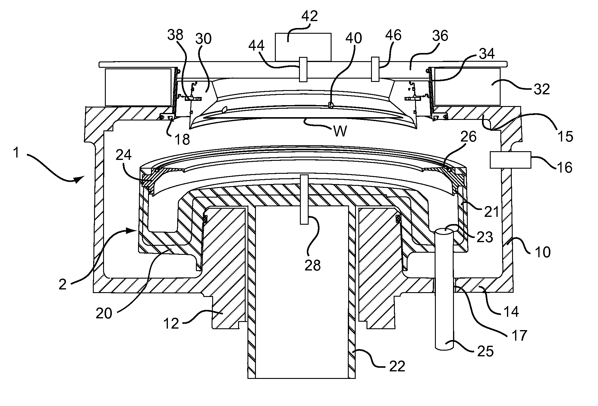
[0034]Referring now to FIG. 1, an apparatus for treating surfaces of wafer-shaped articles according to the invention comprises an outer process chamber 1, which is preferably made of aluminum coated with PFA (perfluoroalkoxy) resin. The chamber in this embodiment has a main cylindrical wall 10, a lower part 12 and an upper part 15. From upper part 15 there extends a narrower cylindrical wall 34, which is closed by a lid 36.

[0035]A rotary chuck 30 is disposed in the upper part of chamber 1, and surrounded by the cylindrical wall 34. Rotary chuck 30 rotatably supports a wafer W during used of the apparatus. The rotary chuck 30 incorporates a rotary drive comprising ring gear 38, which engages and drives a plurality of eccentrically movable gripping members for selectively contacting and releasing the peripheral edge of a wafer W.

[0036]In this embodiment, the rotary chuck 30 is a ring rotor provided adjacent to the interior surface of the cylindrical wall 34. A stator 32 is provided o...

second embodiment

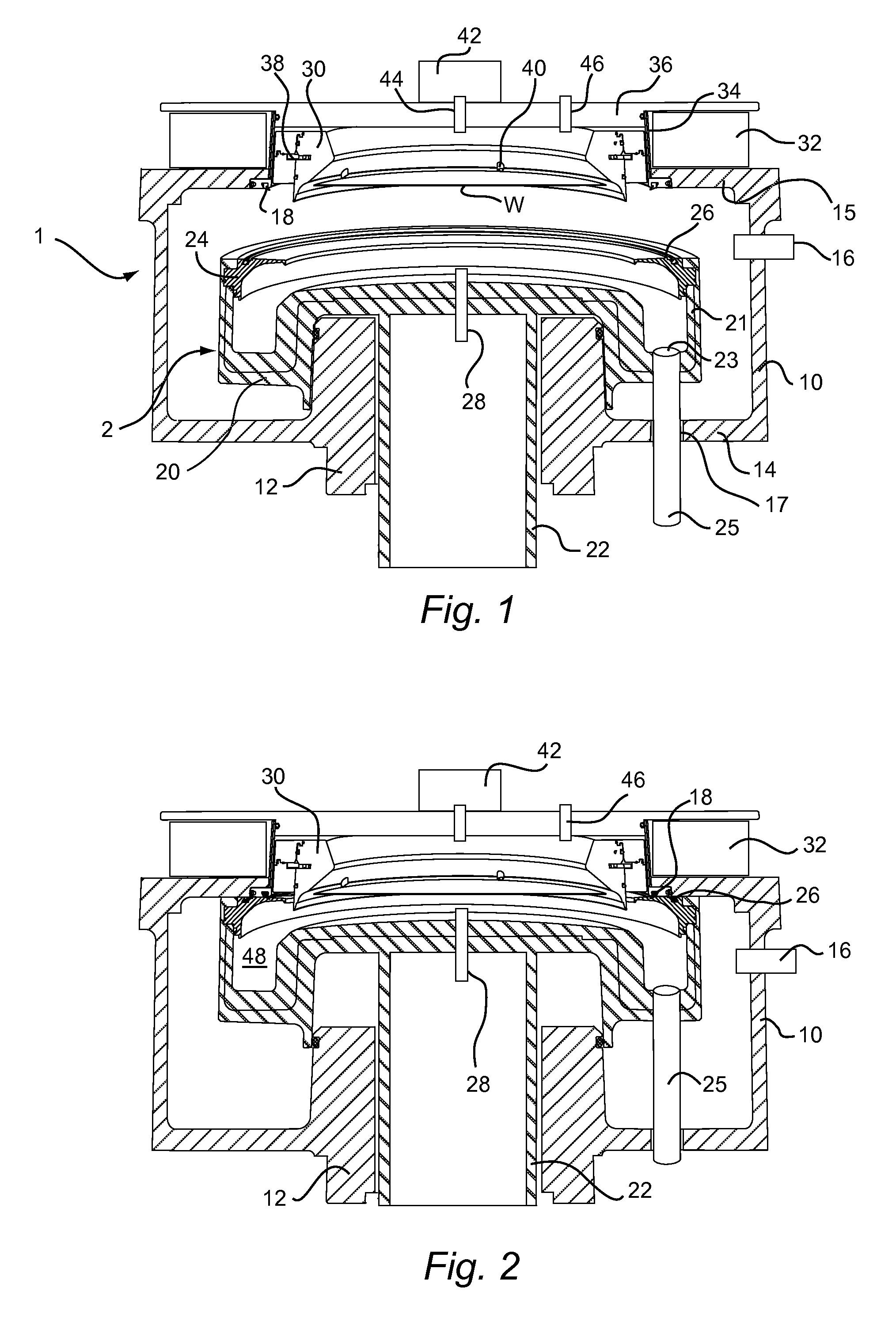
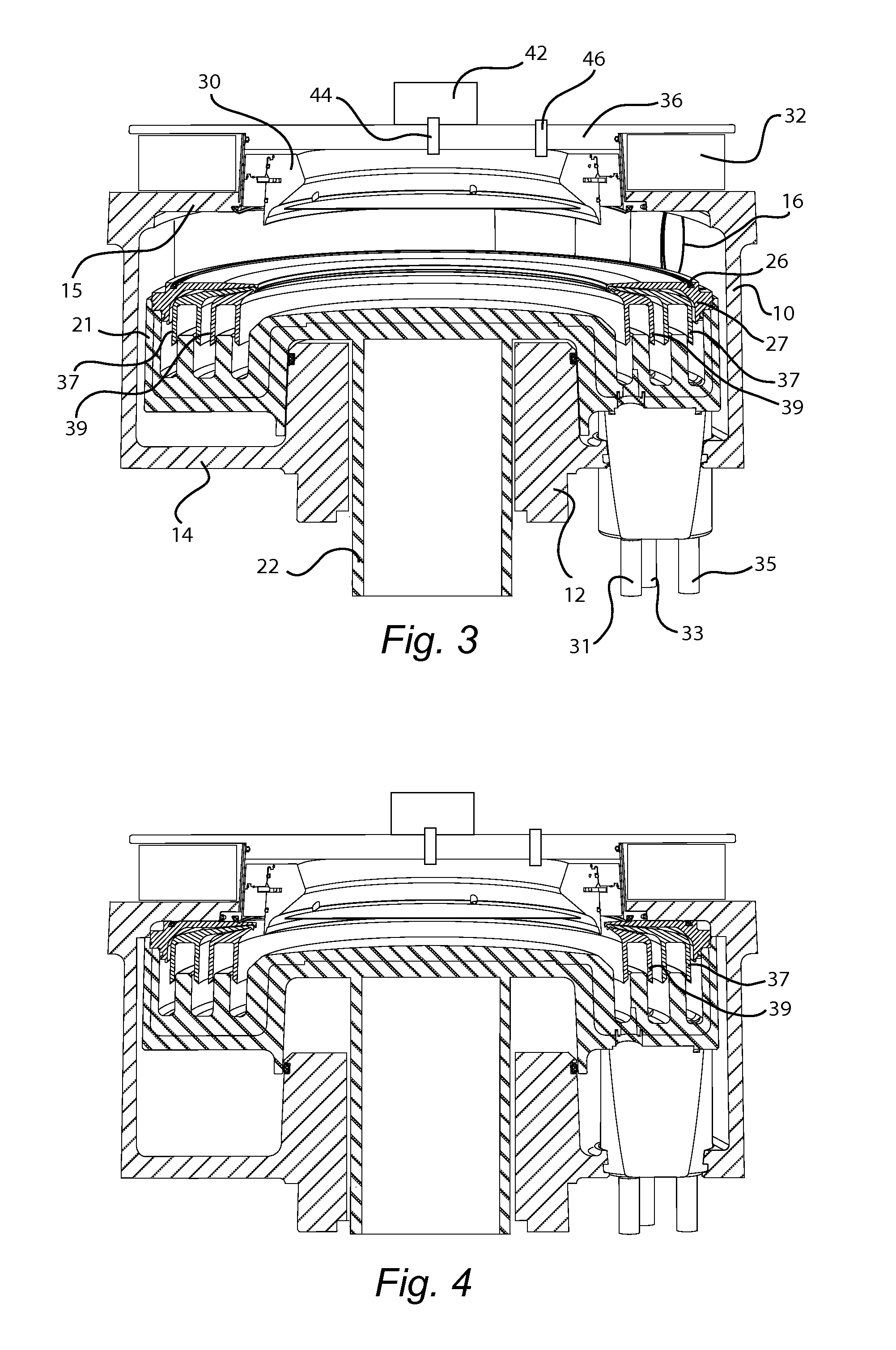
[0049]FIGS. 3-6 show a second embodiment according to the present invention, in which the interior cover 2 is provided with a set of dividers so that separate processing regions can be defined within the inner chamber 48. Specifically, within the interior cover 2, one or more vertically movable splash guards 37, 39. In FIGS. 3-6 two circular splash guards 37 and 39 are shown although it will be appreciated that any desired number of splash guards may be provided and are contemplated by this disclosure, the actual number of splash guards depending in part upon the number of different process fluids which are intended to be separately collected.

[0050]The outer splash guard 37 is positioned concentrically about the inner splash guard 39. Thus, the inner splash guard 39 defines an inner process fluid collector within its interior. A middle process fluid collector is defined by an annular region formed between the outer surface of the inner splash guard 39 and the inner surface of the ou...

fourth embodiment

[0061]FIGS. 9 and 10 show the present invention, in which the spin chuck 50 of the preceding embodiment rotates relative to interior cover 2, but does not move axially relative to the interior cover 2.

[0062]Thus, wafer W is loaded onto spin chuck 50 with interior cover 2 is in the loading / unloading position depicted in FIG. 9, and wafer W is secured in the predetermined orientation relative to chuck 50 by gripping members 40. Interior cover 2 is then moved to its second position as depicted in FIG. 10 and as described above in connection with the first embodiment, to define the inner chamber 48.

[0063]As the spin chuck 50 of this embodiment is not vertically moveable relative to the interior cover 2, the movement of the interior cover 2 serves simultaneously to position wafer W at its final processing position within the chamber 48. Spin chuck 50 is then rotated by a motor (not shown) acting upon shaft 55.


PUM


Abstract

A device for processing wafer-shaped articles comprises a closed process chamber. The closed process chamber comprises a housing providing a gas-tight enclosure, a rotary chuck located within the closed process chamber and adapted to hold a wafer shaped article thereon, and an interior cover disposed within said closed process chamber. The interior cover is movable between a first position in which the rotary chuck communicates with an outer wall of the closed process chamber, and a second position in which the interior cover seals against an inner surface of the closed process chamber adjacent the rotary chuck to define a gas-tight inner process chamber.

Description

BACKGROUND OF THE INVENTION[0001]1. Field of the Invention[0002]The invention relates generally to an apparatus for treating surfaces of wafer-shaped articles, such as semiconductor wafers, wherein one or more treatment fluids may be recovered from within a closed process chamber.[0003]2. Description of Related Art[0004]Semiconductor wafers are subjected to various surface treatment processes such as etching, cleaning, polishing and material deposition. To accommodate such processes, a single wafer may be supported in relation to one or more treatment fluid nozzles by a chuck associated with a rotatable carrier, as is described for example in U.S. Pat. Nos. 4,903,717 and 5,513,668.[0005]Alternatively, a chuck in the form of a ring rotor adapted to support a wafer may be located within a closed process chamber and driven without physical contact through an active magnetic bearing, as is described for example in International Publication No. WO 2007 / 101764 and U.S. Pat. No. 6,485,531....

Claims


Application Information

Patent Timeline
IPC IPC(8): H01L21/687
CPCH01L21/67051Y10T279/3493H01L21/6719H01L21/6708H01L21/67023H01L21/68785
Inventor TSCHINDERLE, ULRICHGLEISSNER, ANDREASWIRNSBERGER, THOMASOBWEGER, RAINER
Owner LAM RES AG
Why Eureka
Try Eureka