Zoom flash with no moving parts

a flash and no moving parts technology, applied in the field of flash photography, can solve the problems of not being easily adaptable, requiring mechanical movement at least some level, and adding significant cost to the flash system, so as to achieve the effect of saving power, reducing the illuminated area in the scene, and increasing the zoom setting

Inactive Publication Date: 2013-03-14
INTELLECTUAL VENTURES FUND 83 LLC
View PDF9 Cites 96 Cited by
  • Summary
  • Abstract
  • Description
  • Claims
  • Application Information

AI Technical Summary

Benefits of technology

[0017]This invention has the advantage that power is conserved during flash operations as the illuminated area in the scene is reduced as the zoom setting is increased.
[0018]It has the additional advantage that the flash unit is simple and can be made very thin.

Problems solved by technology

A disadvantage to this method is that the flash lamp (or one or more components of the illumination optics) must be mechanically moved, which adds significant cost to the flash system.
Yet another technique involves changing the illumination angle of the flash by varying the relationship of a pair of wave lenses, as disclosed in commonly-assigned U.S. Pat. No. 5,666,564 to Albrecht, entitled “Zoom flash with wave-lens.” While these and related methods have merit for adapting the flash illumination angle for many applications, they require at least some level of mechanical movement and may not be easily adaptable, particularly for compact cameras.
However, this approach requires the use of a variable focus lens which is costly.
The illumination pattern provided by the linear array of LEDs is not suited to switching between telephoto and wide angle imaging.
In this patent, each LED illuminates a different portion of the scene so that providing sufficient illumination for a telephoto image is difficult and nonuniformity of illumination is an issue due to the many overlapped illumination regions between the LEDs.

Method used


Image

  • Zoom flash with no moving parts
  • Zoom flash with no moving parts
  • Zoom flash with no moving parts

Examples


Embodiment Construction

[0032]The invention is inclusive of combinations of the embodiments described herein. References to “a particular embodiment” and the like refer to features that are present in at least one embodiment of the invention. Separate references to “an embodiment” or “particular embodiments” or the like do not necessarily refer to the same embodiment or embodiments; however, such embodiments are not mutually exclusive, unless so indicated or as are readily apparent to one of skill in the art. The use of singular or plural in referring to the “method” or “methods” and the like is not limiting. It should be noted that, unless otherwise explicitly noted or required by context, the word “or” is used in this disclosure in a non-exclusive sense.

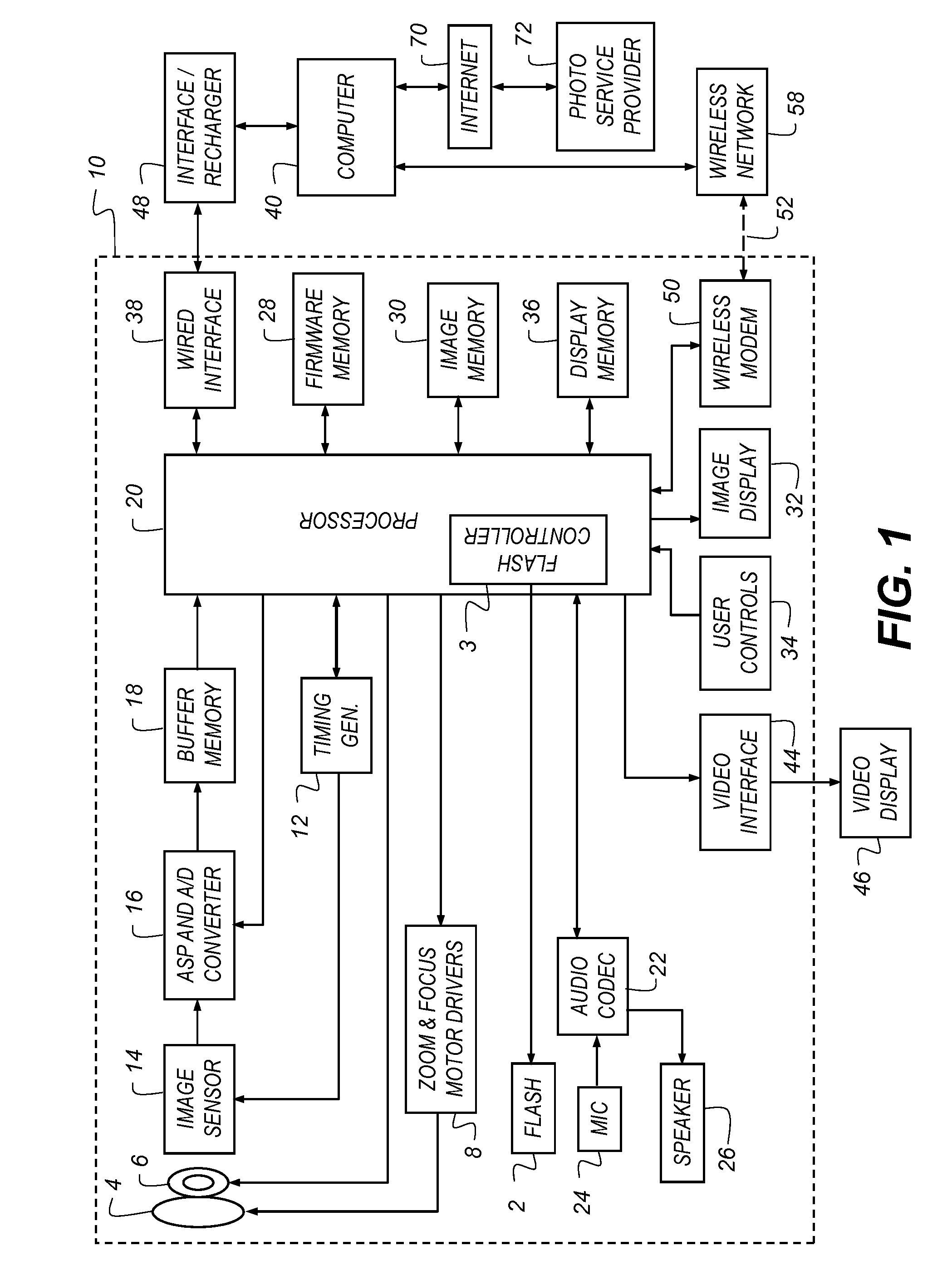
[0033]Because digital cameras employing imaging devices and related circuitry for signal capture and processing, and display are well known, the present description will be directed in particular to elements forming part of, or cooperating more directly w...


PUM


Abstract

A camera system having an electronic flash with a variable illumination angle, comprising: an image forming system having a user-selectable field-of-view for forming an image of a scene onto an image plane; an electronic flash system including a plurality of fixed focal length illumination lenses having two or more different focal lengths and one or more light emitters positioned behind each of the illumination lenses, the light emitters being positioned relative to their respective illumination lenses to provide two or more different illumination angles onto the scene; and a flash controller that selectively fires different subsets of the light emitters responsive to the selected field-of-view of the image forming system.

Description

FIELD OF THE INVENTION[0001]This invention pertains to the field of flash photography and more particularly to flash photography for a camera having zoom capability.BACKGROUND OF THE INVENTION[0002]When operating a digital camera in a flash mode, flash illumination is provided to a scene during image capture. The flash illumination is typically provided by a built-in electronic flash unit. When the digital camera has a zoom lens, or incorporates a digital zoom feature, the field-of-view included in the digital image of the scene is selectable by the user.[0003]To conserve power and enable brighter images of the scene to be captured, it is advantageous to match the scene area illuminated by the flash to the selected field-of-view included in the digital image. For digital cameras having a zoom capability, it is therefore desirable that the scene area illuminated by the flash must be adjustable. In this way, when the selected field-of-view is small (corresponding to a telephoto zoom s...

Claims


Application Information

Patent Timeline
Patent Type & Authority Applications(United States)
IPC IPC(8): G03B15/05
CPCH04N5/23296H04N5/2256H04N5/2354H04N23/56H04N23/69H04N23/74
Inventor PILLMAN, BRUCE HAROLDBORDER, JOHN NORVOLDBIETRY, JOSEPH RAYMOND
Owner INTELLECTUAL VENTURES FUND 83 LLC
Why Eureka
Try Eureka