Direct acting extensible and retractable arm mechanism, and robot arm provided with direct acting extensible and retractable arm mechanism

a technology of retractable arm and retractable arm, which is applied in the direction of chain elements, gearing, program-controlled manipulators, etc., can solve the problems of inapplicability of arrangement to robot arms, robot arms are dangerous, and cannot be determined arbitrarily, and achieve high rigidity

Active Publication Date: 2013-03-21
FANUC LTD +1
View PDF7 Cites 90 Cited by
  • Summary
  • Abstract
  • Description
  • Claims
  • Application Information

AI Technical Summary

Benefits of technology

[0020]As described above, a direct acting extensible and retractable arm mechanism of the present invention includes: a robot arm supporting member; a robot arm supporting member; and an arm section being extensible and retractable directly from one of ends of the robot arm supporting member, the arm section being such that a hand section is attachable to one of ends of the arm section, the arm section being constituted by (i) a first structure group in which a plurality of first structures are coupled with each other in series in such a manner that adjacent ones of the plurality of first structures are coupled with each other via a corresponding one of a plurality of first coupling axes in a direction which is orthogonal to a direction of the corresponding one of the plurality of first coupling axes and (ii) a second structure group in which a plurality of second structures are coupled with each other in series in such a manner that adjacent ones of the plurality of second structures are coupled with each other via a corresponding one of a plurality of second coupling axes in a direction which is orthogonal to a direction of the corresponding one of the plurality of second coupling axes, the plurality of first structures being identical with each other in width in a direction parallel to the plurality of first coupling axes, the plurality of second structures being identical with each other in width in a direction parallel to the plurality of second coupling axes, the first structure group and the second structure group being coupled with each other in such a manner that one of two end first structures of the plurality of first structures, on a hand section side, and one of two end second structures of the plurality of second structures, on the hand section side, are coupled with each other, the robot arm supporting member including drive means for (i) pressing the first structure group and the second structure group so that the first structure group and the second structure group become closer to each other and become in contact with each other, (ii) causing the first structure group and the second structure group to overlap each other so that a surface of the first structure group and a surface of the second structure group, which surf

Problems solved by technology

That is, there is a problem that it is not possible to determine arbitrarily the position of the end effector 101 and a position of each of the rotational joints 103.
Such an arrangement is not suitably applicable to a robot arm which operates in the vicinity of a person in a daily life or the like.
However, such a robot arm has danger in a case where the robot arm operates in the vicinity of a human in a daily life or the like.
That is, there remains danger for a human in a case where the direct acting mechanism operates in the vicinity of the human in a

Method used


Image

  • Direct acting extensible and retractable arm mechanism, and robot arm provided with direct acting extensible and retractable arm mechanism
  • Direct acting extensible and retractable arm mechanism, and robot arm provided with direct acting extensible and retractable arm mechanism
  • Direct acting extensible and retractable arm mechanism, and robot arm provided with direct acting extensible and retractable arm mechanism

Examples


modified example 1

of the Present Embodiment

[0148]As a matter of course, the extensible and retractable arm mechanism can be altered variously. For example, shapes of the upper structure 22 and the lower structure 23, or a method of causing the arm section 2 to have a rigid structure can be changed.

[0149]For example, a length of the upper structure 22 in the longitudinal direction can be shorter than a length of the lower structure 23 in the longitudinal direction, as illustrated in FIG. 14.

[0150]Alternatively, the length of the upper structure 22 in the longitudinal direction can be longer than the length of the lower structure 23 in the longitudinal direction, as illustrated in FIG. 15.

[0151]The lower structure group 21 is such that adjacent ones of the plurality of lower structures are coupled with each other via only a pin 30. For this reason, it is possible that, in a case where (i) adjacent ones of the plurality of lower structures 23 are arranged to be connected to each other in series such tha...

modified example 2

of the Present Embodiment)

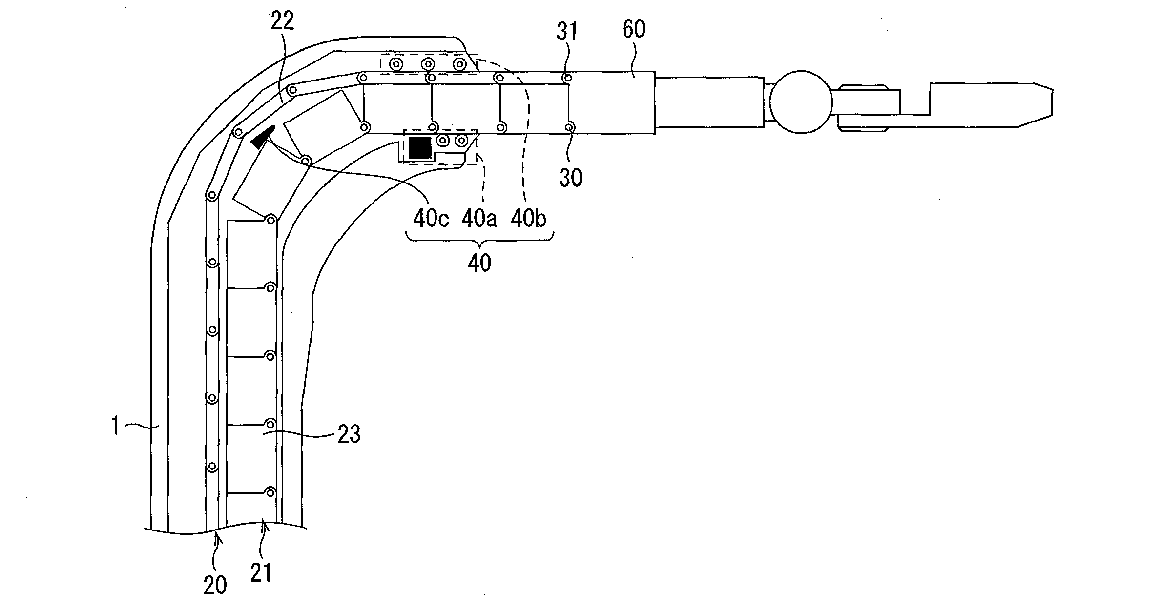
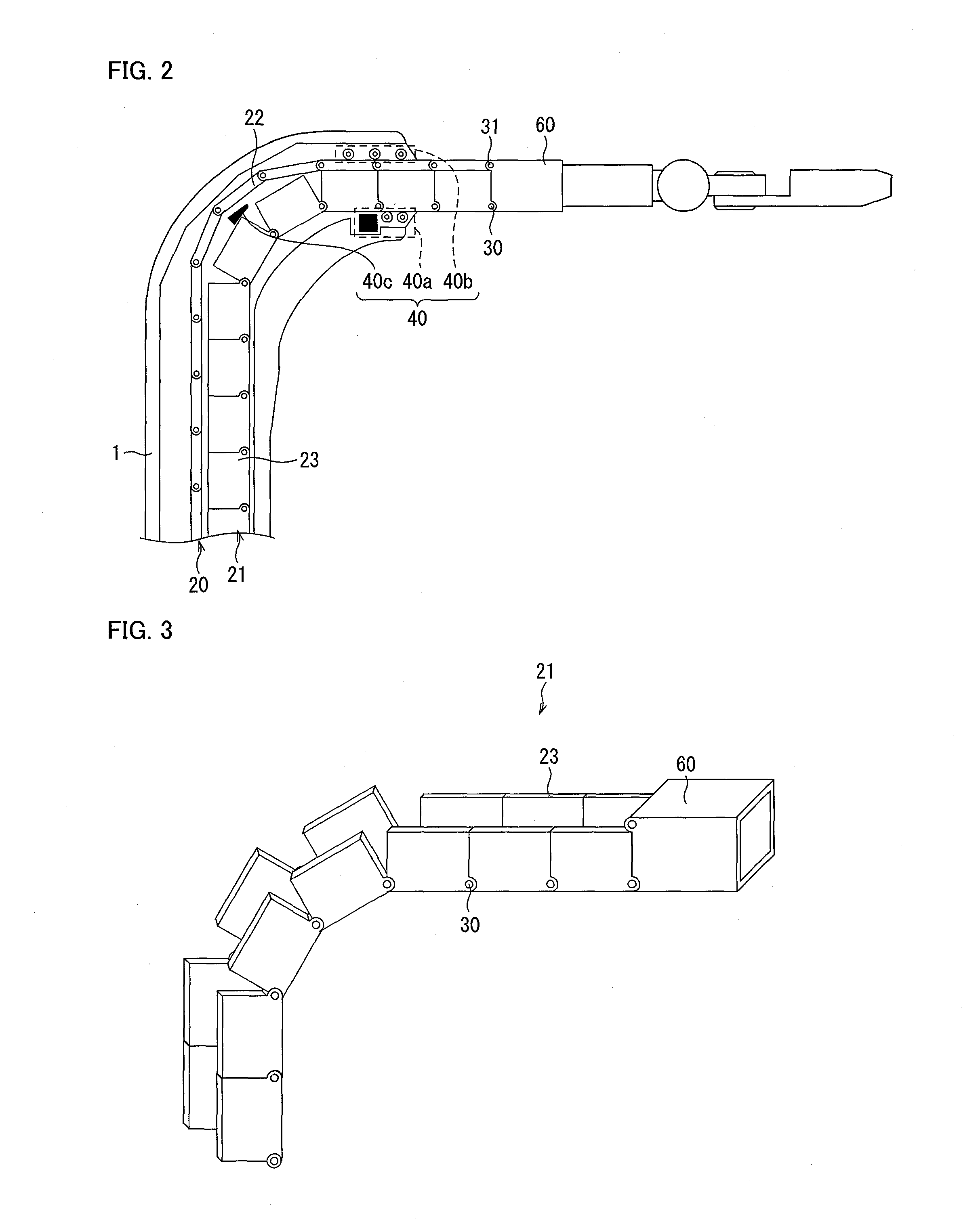
[0152]According to the present embodiment, as illustrated in FIG. 7, (i) the drive means 40a for the lower structure group includes the drive mechanism 33 that is constituted by (a) the gear 34 which engages with the bottom surface convex-concave structure 23a of each of the plurality of lower structures 23, and (b) the actuator 35 for driving the gear 34, and the drive means 40a is provided below each of the plurality of lower structures 23, (ii) the drive means 40b for the upper structure group includes the drive mechanism that is constituted by (a) the gear which engages with the upper convex-concave structure of each of the plurality of upper structures 22 and (b) the actuator for driving the gear, and the drive means 40b is provided above each of the plurality of upper structures 22, and (iii) the driving is carried out by use of at least one of the drive means 40a and the drive means 40b. Note, however, that the present invention is not limited to thi...

modified example 2-(

f)

[0162]Modified Example 2-(f) is such that, in addition to the upper gear 34 and the lower gear 34 of Modified Example 2-(a), provided on the right side, another upper gear 34 and another lower gear 34 are further provided on the left side.

[0163]According to Modified Examples 2-(a) through 2-(f), the gear 34 and the drive mechanism are provided at least one of (i) on the left side of the arm section and (ii) on the right side of the arm section. With the arrangement, it is possible to avoid an influence of gravitational force, as compared with the arrangement in which the gear 34 and the drive mechanism are provided at an upper position and a lower position, respectively. Specifically, in a case where the gear 34 and the drive mechanism are provided at the upper position and lower position, respectively, as illustrated in FIG. 7, there is an influence, such as force and torque, on the drive means due to gravitational force (gravitational force related to the arm section). This migh...


PUM


Abstract

A robot arm (50) of the present invention includes, as a direct acting extensible/retractable joint (J3), an arm section (2) constituted by an upper structure group (20) and a lower structure group (21). Groups (20) and (21), having an arrangement in which structures are connected in series, partially engage so as to form a direct rigid combined structure, and are separated so as to release the rigid structure. An arm length can be adjusted arbitrarily. Section (2) can have a plane surface having no gap to prevent entry of a finger/dust. Separation of Groups (20) and (21) allows an upper structure (22) and a lower structure (23) to rotate around their rotational axes, to realize compact storage inside a robot arm supporting member (1). It is thus possible to prevent significantly entry of a finger/dust, and provide a compact direct acting extensible and retractable arm mechanism.

Description

TECHNICAL FIELD[0001]The present invention relates to a mechanism of a robot arm. Specifically, the present invention relates to (i) a direct acting extensible and retractable arm mechanism which realizes high safety, a compact body, and prevention of entry of dust and the like, and (ii) a robot arm including the direct acting extensible and retractable arm mechanism.BACKGROUND ART[0002]In recent years, there has been a reduction in population of workers in an aging society with a falling birthrate. Because of such a reduction in population of workers, there has been demand for a robot arm which (i) can manufacture a product in cooperation with a human at a production site or (ii) can support a daily life of an old person or a daily life of a handicapped person.[0003]A robot arm constituted by rotational joints has an arrangement in which a plurality of rotational joints 103 and a plurality of arm sections 102 are, alternately, connected to each other in series between a base 100 an...

Claims


Application Information

Patent Timeline
IPC IPC(8): B25J18/06B25J9/06
CPCB25J18/025B25J18/06F16G13/20Y10T74/20329B25J9/06Y10S901/25F16H19/0636B25J17/00B25J18/02Y10S901/28
Inventor YOON, WOO-KEUN
Owner FANUC LTD
Why Eureka
Try Eureka