Lighting device, display device and television device
- Summary
- Abstract
- Description
- Claims
- Application Information
AI Technical Summary
Benefits of technology
Problems solved by technology
Method used
Image

Examples
first embodiment
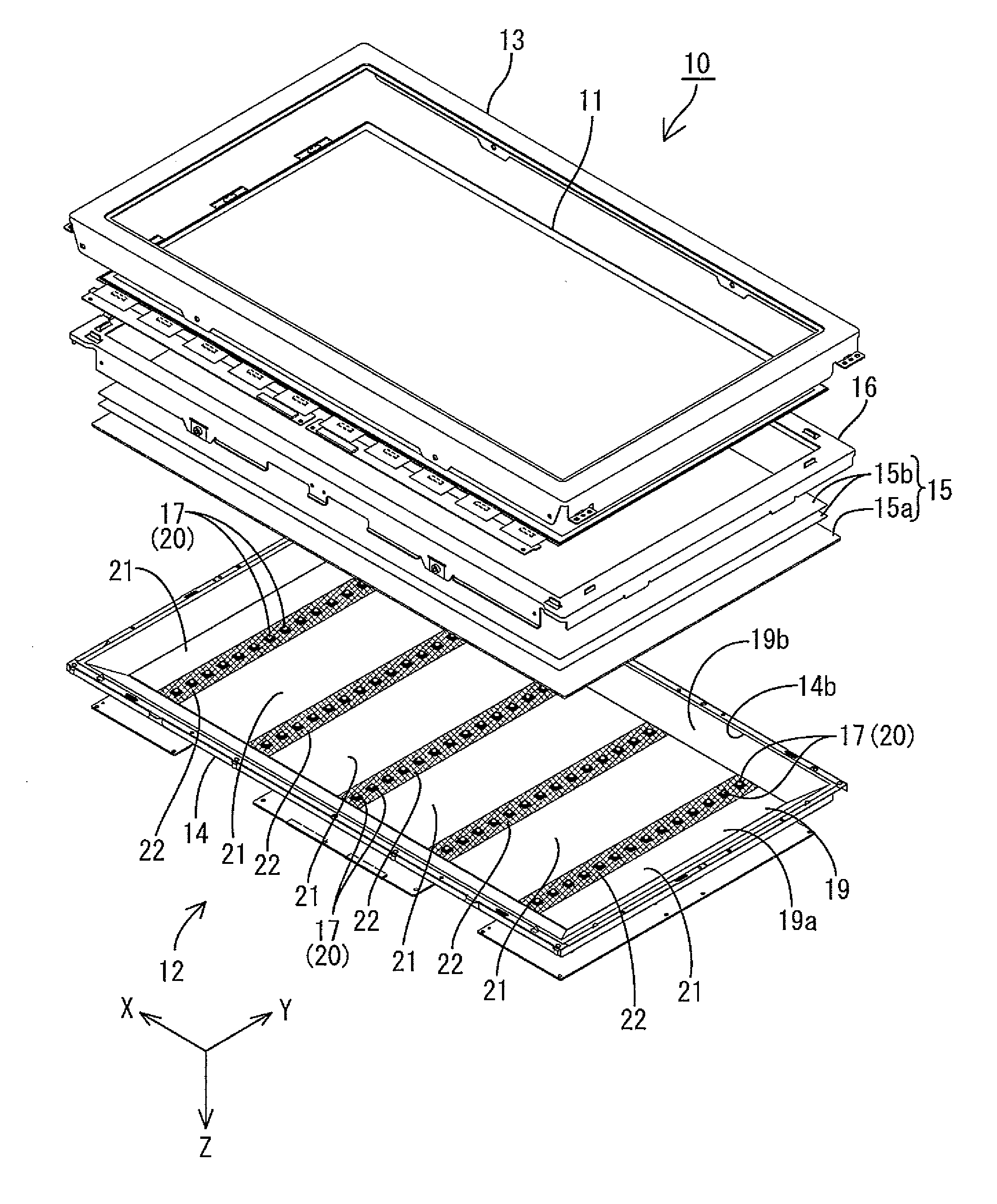
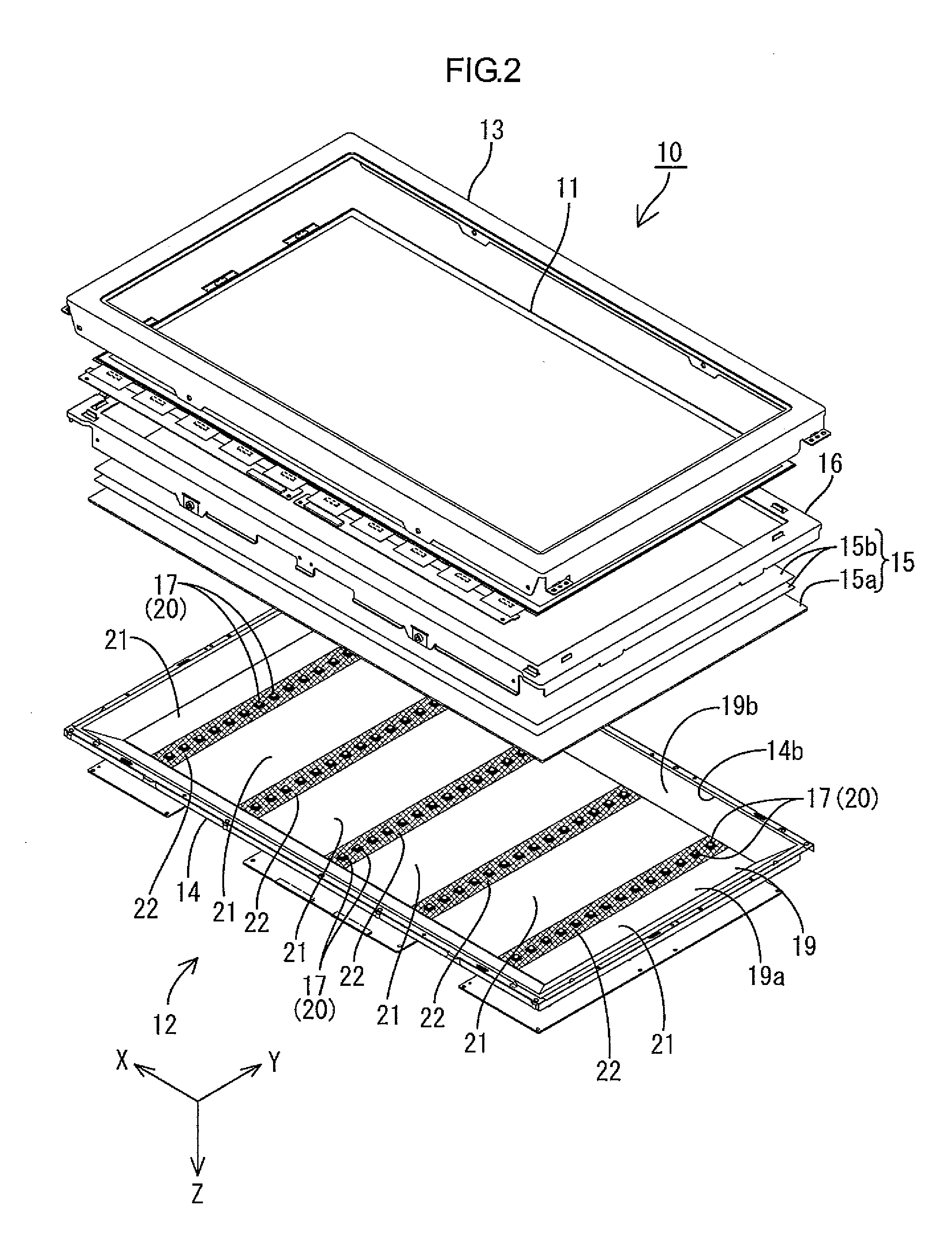
[0055]A first embodiment of the present invention will be described with reference to FIGS. 1 to 7. In the present embodiment, a liquid crystal display device 10 will be illustrated. It is to be noted that some of the drawings have X, Y and Z axes shown therein such that the respective axial directions are directed in common in the respective drawings. Also, the upper side in each of FIGS. 4 and 5 corresponds to a front side and the lower side corresponds to a back side.
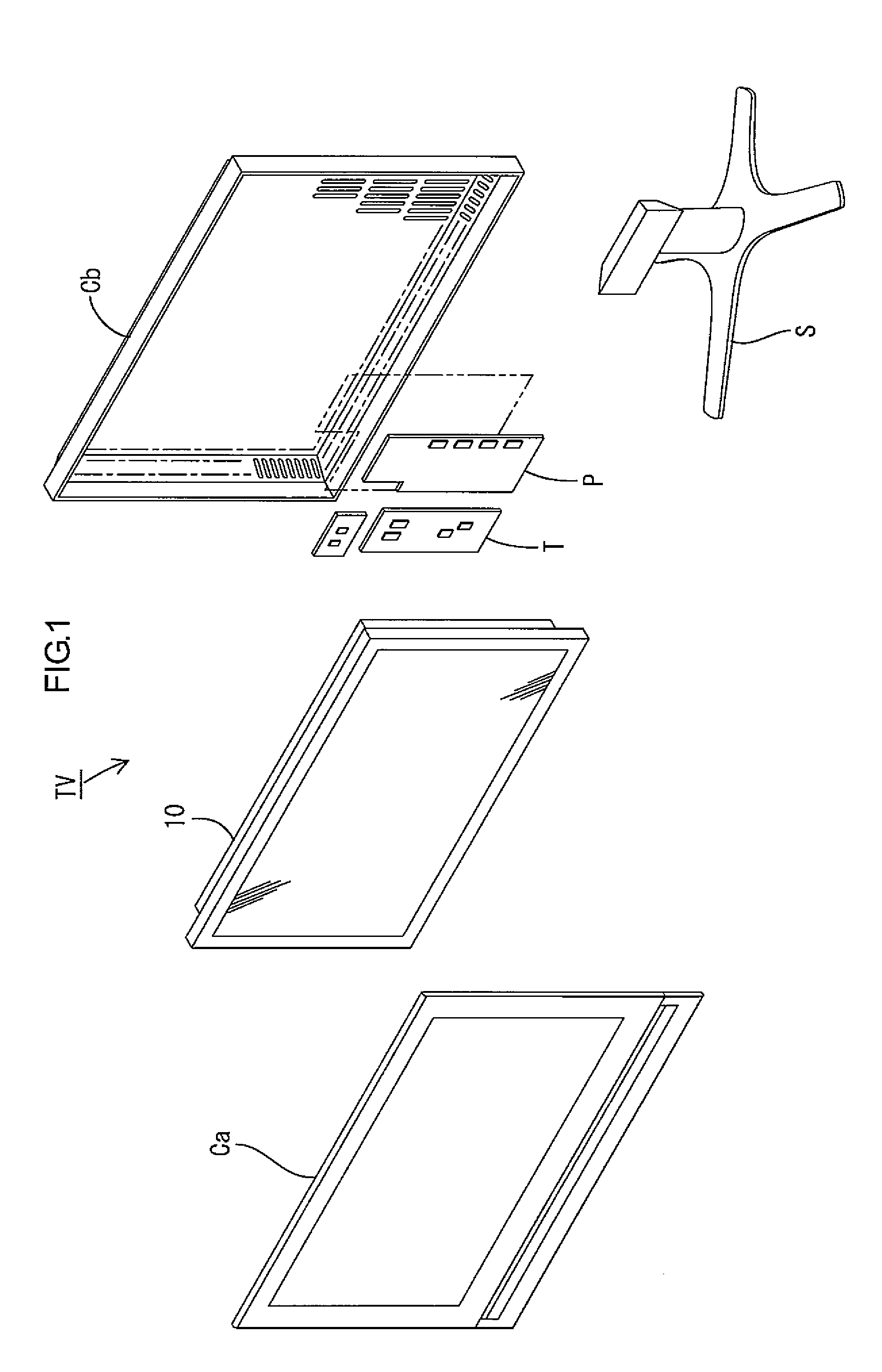
[0056]A television device TV according to the present embodiment includes the liquid crystal display device 10, front and back cabinets Ca and Cb housing the liquid crystal display device 10 so as to sandwich the liquid crystal display device 10 inbetween, a power source P, a tuner T and a stand S, as illustrated in FIG. 1. The liquid crystal display device (display device) 10 is formed in a horizontally long (elongated) square shape (long rectangular shape) as a whole and is housed in a vertically-placed state. As i...
first modification
of First Embodiment
[0095]A first modification of the first embodiment will be described with reference to FIG. 8. In this example, arrangement of LED boards 18-1 is changed.
[0096]Each LED board 18-1 according to the present modification is formed in a horizontally long shape and is arranged in the chassis 14 in a posture in which a length direction thereof is aligned with the X axial direction or the longer side direction of the chassis 14 (reflection sheet 19-1) and in which a width direction thereof is aligned with the Y axial direction or the shorter side direction of the chassis 14 as illustrated in FIG. 8. The LED board 18-1 lies across the entire area of the bottom plate 14a (bottom portion 19a-1) of the chassis 14 along the longer side direction of the bottom plate 14a. Three LED boards 18-1 are arranged intermittently in the Y axial direction. Accordingly, on the bottom portion 19a-1 of the reflection sheet 19-1, each of the light source arranging areas LA, that is the low l...
second modification
of First Embodiment
[0097]A second modification of the first embodiment will be described with reference to FIG. 9. In this example, a shape and size of an LED board 18-2 are changed.
[0098]The LED board 18-2 according to the present modification is formed in a horizontally long shape and is one size larger than the bottom plate 14a (bottom portion 19a) of the chassis 14 (reflection sheet 19) as illustrated in FIG. 9. That is, the LED board 18-2 is large so as to be arranged approximately over the entire area of the bottom plate 14a (bottom portion 19a). On the LED board 18-2, the plurality of LEDs 17 constituting the respective LED groups 20 is arranged along the Y axial direction.
PUM
 Abstract
Description
Claims
Application Information
 - R&D
- Intellectual Property
- Life Sciences
- Materials
- Tech Scout
- Unparalleled Data Quality
- Higher Quality Content
- 60% Fewer Hallucinations
Browse by: Latest US Patents, China's latest patents, Technical Efficacy Thesaurus, Application Domain, Technology Topic, Popular Technical Reports.
© 2025 PatSnap. All rights reserved.Legal|Privacy policy|Modern Slavery Act Transparency Statement|Sitemap|About US| Contact US: help@patsnap.com