Quick-release fixing structure for electronic equipments

Active Publication Date: 2013-03-21
GRAND TEK TECH
View PDF17 Cites 6 Cited by
  • Summary
  • Abstract
  • Description
  • Claims
  • Application Information

AI Technical Summary

Benefits of technology

[0008]The present invention has the following effects. The electronic equipment can be fixed to a rod or a wall selectively by using the support frame or the locking hole of the substrate to provide more disposing positions of the electronic equipment, so that the quick-release fixing structure of the present invention features a very

Problems solved by technology

For example, when an antenna case is installed indoors, the antenna case is usually adjusted to the best position for receiving signals, so that the installation positions of the antenna case may be bizarre; and when the antenna case is installed outdoors, the antenna case is usually installed at a high place for receiving the signals, so that most antenna cases are installed at positions such as a street lamp pole, an attic wall or a railing.
However, if the antenna case fails to receive signals and it is necessary to switch the position of the installed antenna case, or inspect, maintain or repair the anten

Method used


Image

  • Quick-release fixing structure for electronic equipments
  • Quick-release fixing structure for electronic equipments
  • Quick-release fixing structure for electronic equipments

Examples


Embodiment Construction

[0018]The technical contents of the present invention will become apparent with the detailed description of preferred embodiments accompanied with the illustration of related drawings as follows. It is noteworthy that the drawings are provided for the purpose of illustrating the present invention only, but not intended for limiting the scope of the invention.

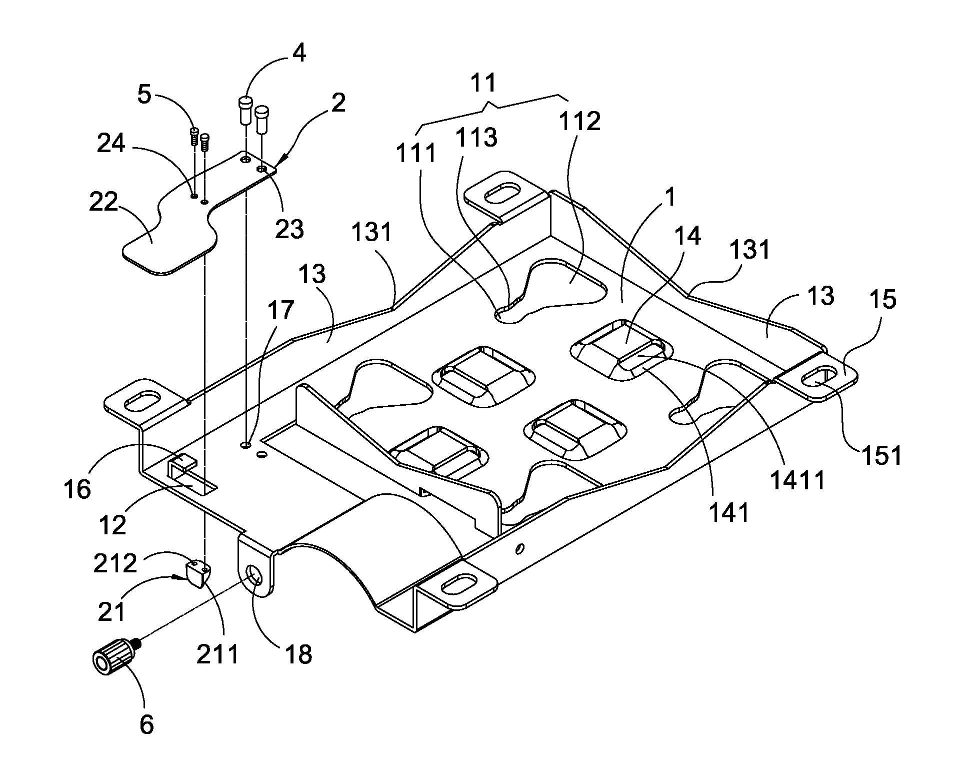
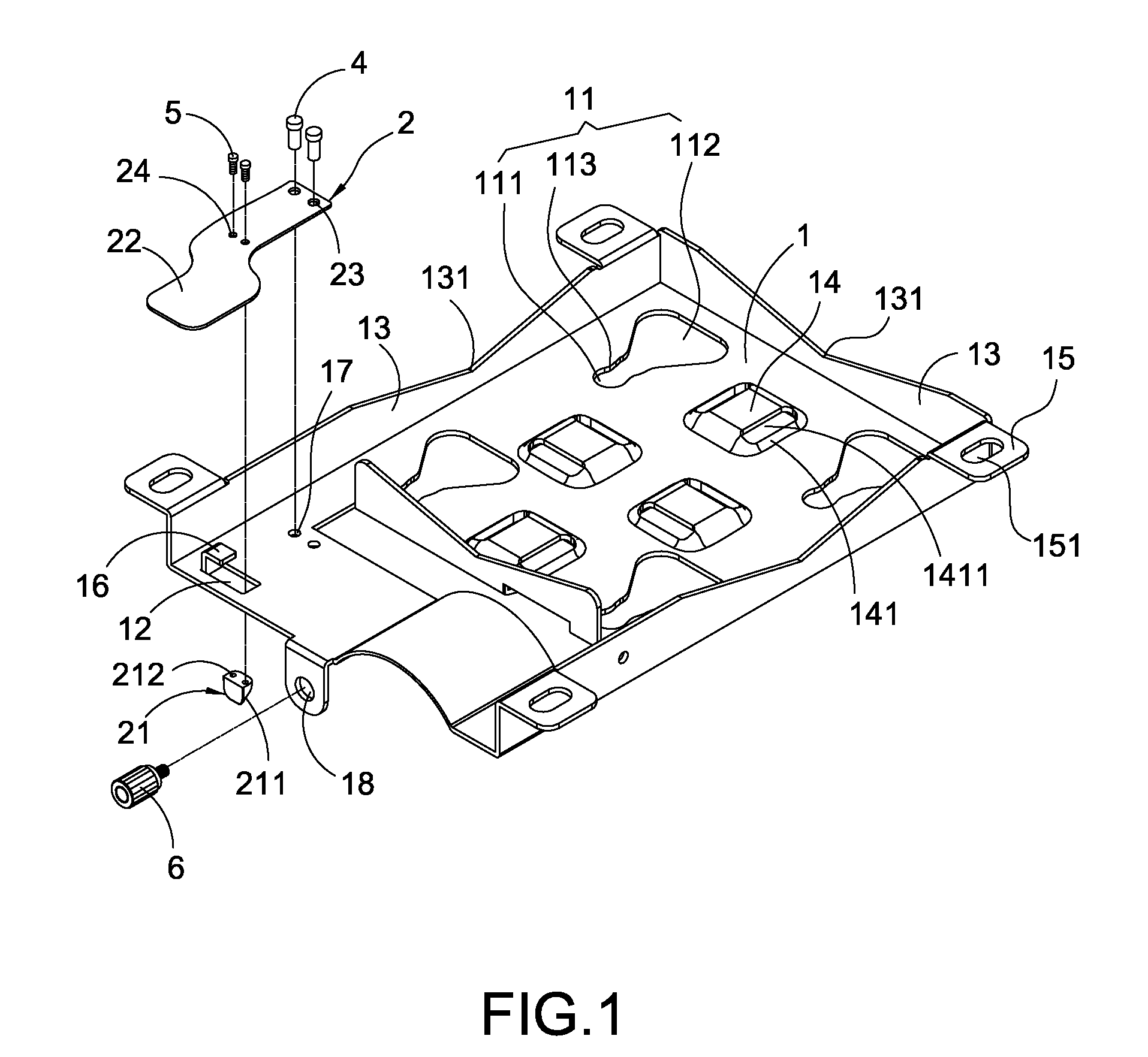
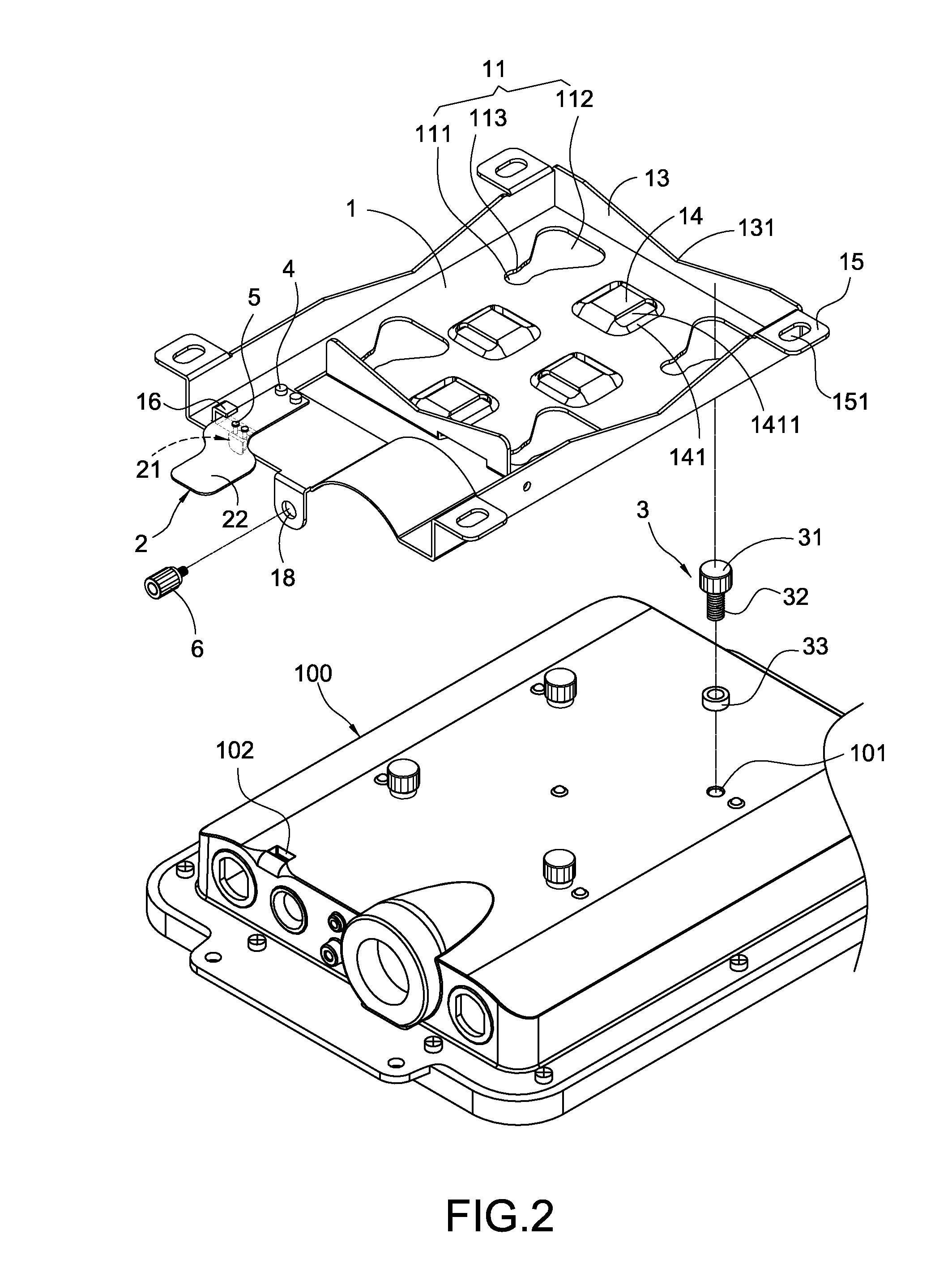
[0019]With reference to FIGS. 1 to 3 for a quick-release fixing structure for an electronic equipment in accordance with the present invention, the electronic equipment 100 has a plurality of holes 101 and a snap slot 102, and the quick-release fixing structure comprises a substrate 1, a turning element 2 and a plurality of fixing elements 3.

[0020]The substrate 1 includes a plurality of grooves 11 and a port 12, and each groove 11 includes a first groove hole 111 and a second groove hole 112 interconnected to the first groove hole 111, and the second groove hole 112 has a size greater than the first groove hole 111, and the subs...


PUM


Abstract

In a quick-release fixing structure for an electronic equipment, the electronic equipment includes a plurality of holes and a snap slot, and the quick-release fixing structure includes a substrate, a turning element and a plurality of fixing elements. The substrate includes a plurality of grooves and a port, and each groove includes a first groove hole and a second groove hole interconnected to the first groove hole, and the second groove hole is greater than the first groove hole. The turning element is coupled to the substrate and includes a bump exposed from the port and snapped into the snap slot. Each fixing element is passed through each first groove hole and fixed to each hole. The turning element can be turned to push the electronic equipment to move each fixing element into each second groove hole, and separate the electronic equipment from the substrate.

Description

FIELD OF THE INVENTION[0001]The present invention relates to a fixing structure for fixing electronic equipments on a wall or a rod, in particular to a quick-release fixing structure for electronic equipments.BACKGROUND OF THE INVENTION[0002]Present electronic equipments sometimes have to be installed on a wall or a rod. For example, when an antenna case is installed indoors, the antenna case is usually adjusted to the best position for receiving signals, so that the installation positions of the antenna case may be bizarre; and when the antenna case is installed outdoors, the antenna case is usually installed at a high place for receiving the signals, so that most antenna cases are installed at positions such as a street lamp pole, an attic wall or a railing.[0003]Since the antenna cases are installed at places without a specific regularity regardless of its installation indoors or outdoors, therefore users have to fix the antenna case to a desired place on their own. In general, m...

Claims


Application Information

Patent Timeline
IPC IPC(8): F16D1/108
CPCF16B5/07Y10T403/32975H05K5/0204F16B21/09
Inventor CHEN, CHIA-JUNGLIN, YU-WEI
Owner GRAND TEK TECH
Why Eureka
Try Eureka