
Transport system powered by short block linear synchronous motors and switching mechanism

a technology of linear synchronous motors and switching mechanisms, applied in transportation and packaging, railway components, roads, etc., can solve the problems of insufficient precise control, inconvenient maintenance, and inability to achieve precise control of the approach,

Active Publication Date: 2013-03-28
ROCKWELL AUTOMATION
View PDF1 Cites 119 Cited by
  • Summary
  • Abstract
  • Description
  • Claims
  • Application Information

AI Technical Summary

Benefits of technology

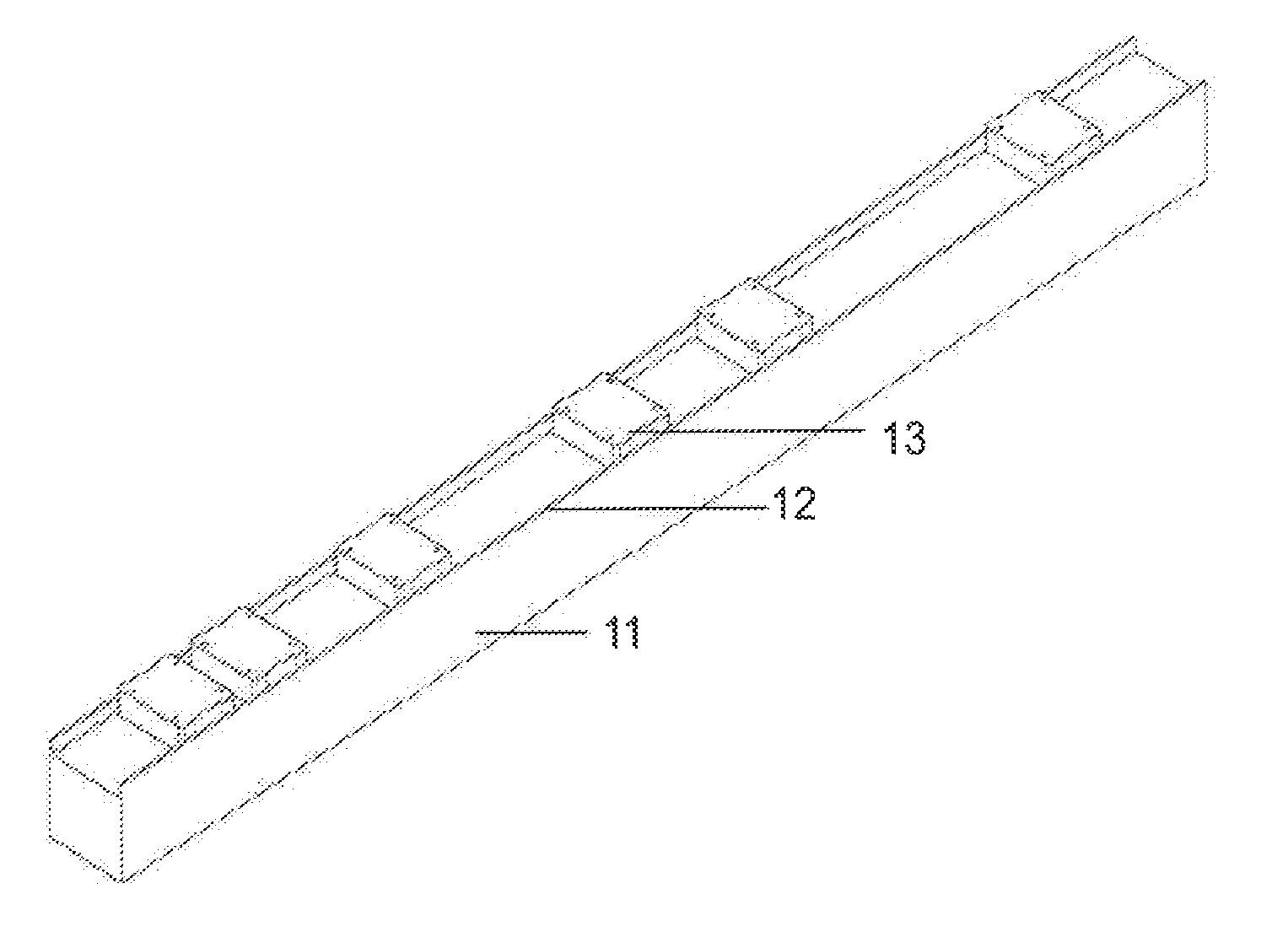
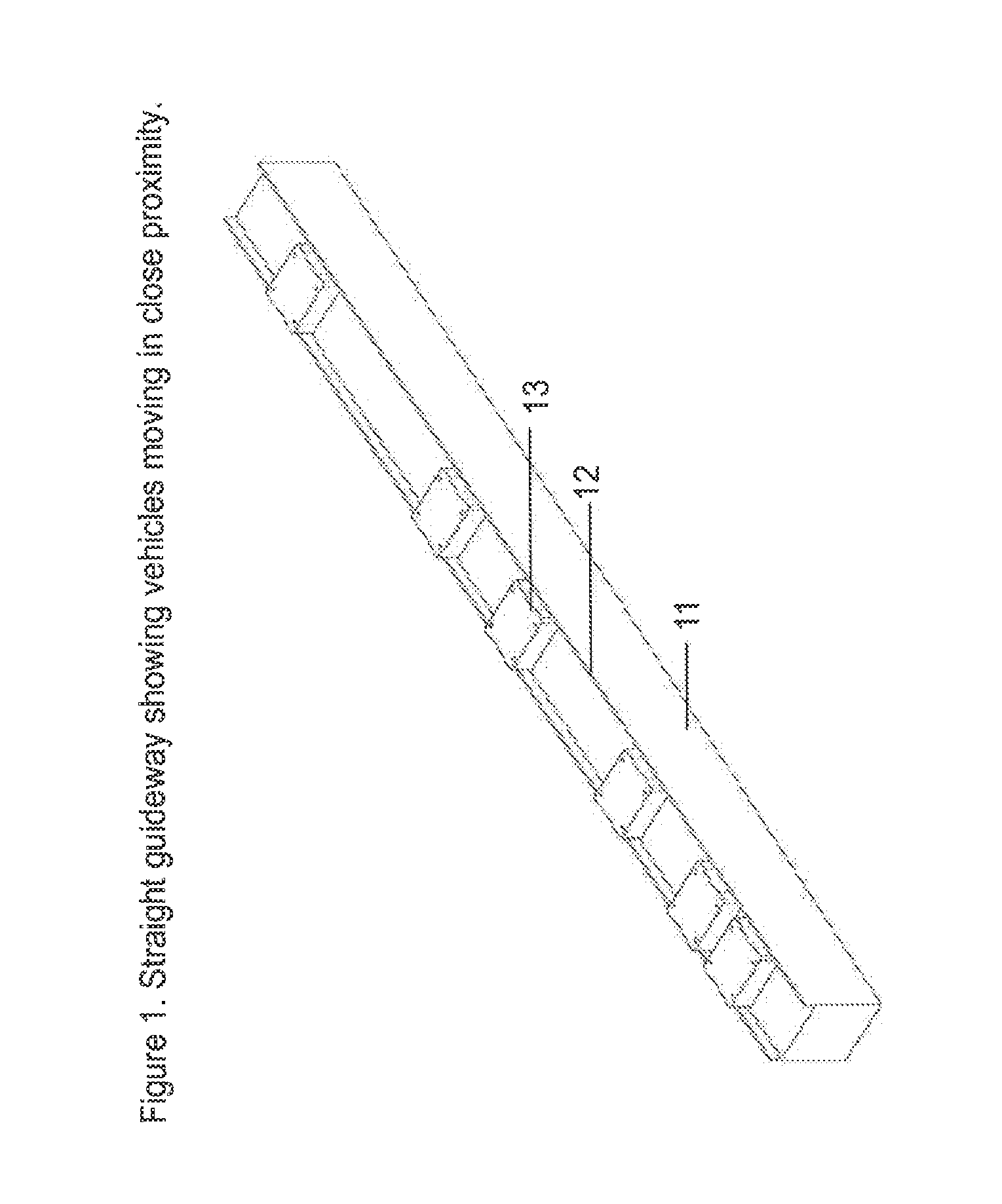
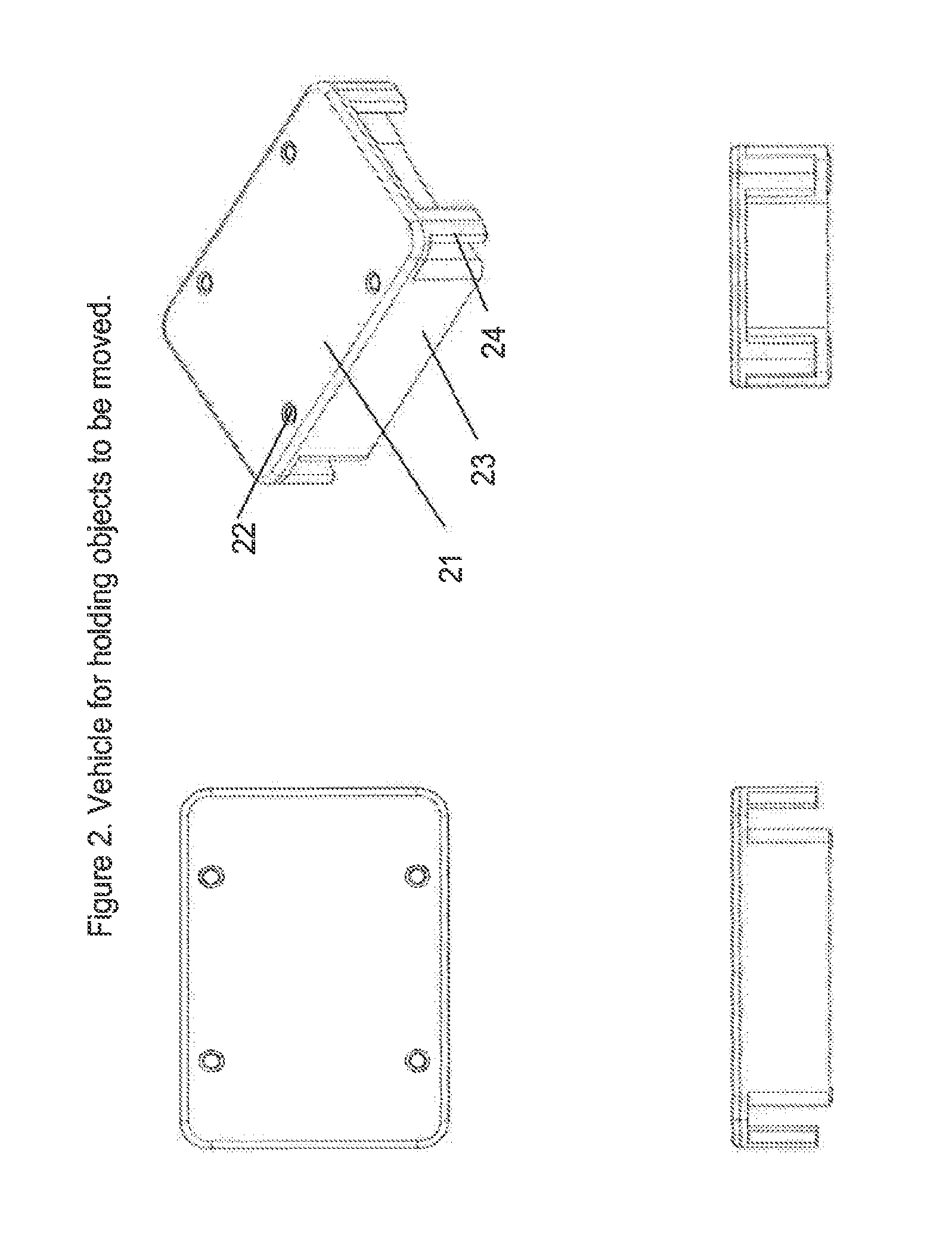
The invention is a transport system that uses a guideway with propulsion coils to move vehicles along a path. The guideway has a diverge region where the vehicles can switch direction. The system includes a flipper that initiates the switching of direction by exerting a lateral force on the vehicle. The flipper can be in contact with the vehicle's body or with the guideway's running surface. The guideway can have guidance surfaces that constrain motion or provide further guidance for switching direction. The vehicles can be small and move at high speeds. The flipper can be mechanically actuated and can be designed for different vehicles and applications. The invention also includes a merge region where the flipper applies a lateral force to the vehicle to control its angle of motion. The vehicles can be of different cross-sections and can be coupled together. The technical effects of the invention include improved control and efficiency of vehicle movement and inspection and assembly of small parts.

Problems solved by technology

Belt transport systems are relatively inexpensive but they lack precise control that is often needed and they require substantial maintenance because of many moving parts.
Other approaches to low cost transport include air propelled vehicle moving in tubes and the use of gravitational forces to move objects down an incline, but these approaches have even less precise control.

Method used


Image

  • Transport system powered by short block linear synchronous motors and switching mechanism
  • Transport system powered by short block linear synchronous motors and switching mechanism
  • Transport system powered by short block linear synchronous motors and switching mechanism

Examples


application example

[0092]There are many possible applications but the simple layout in FIG. 14 shows how the guideway modules can be interconnected. Vehicles move around the main loop but can move though a bypass when desired. Typical applications will use many more guideway modules than in this simple example.

Additional Embodiments

[0093]As evident in FIGS. 1-14, in some embodiments the running or sliding surface of the guideway comprises an upper surface of the guideway immediately adjacent the propulsion coils, for example, as indicated by surface 63 and coils 64 of FIG. 6 and discussed above. In other embodiments, such a running or sliding surface can be another upper-facing (or vehicle-contacting) surface of the guideway for example, a surface of a rail, ledge, recess, or flange of the guideway. That surface can be immediately adjacent to the coils 64 or offset therefrom.

[0094]This is shown, for example, in FIG. 15, wherein surfaces 63A, which are offset from the coils by a distance Δ provide low ...


PUM


Abstract

The invention provides in some aspects a transport system comprising a guideway with a plurality of propulsion coils disposed along a region in which one or more vehicles are to be propelled. One or more vehicles are disposed on the guideway, each including a magnetic flux source. The guideway has one or more running surfaces that support the vehicles and along which they roll or slide. Each vehicle can have a septum portion of narrowed cross-section that is coupled to one or more body portions of the vehicle. The guideway includes a diverge region that has a flipper and an extension of the running surface at a vertex of the diverge. The flipper initiates switching of vehicle direction at a diverge by exerting a laterally directed force thereon.

Description

CROSS REFERENCE AND RELATED APPLICATIONS[0001]The present application is a continuation-in-part of, and claims the benefit of, U.S. patent application Ser. No. 12 / 692,441, filed Jan. 22, 2010, which is a continuation-in-part of, and claims the benefit of U.S. patent application Ser. No. 12 / 359,022, filed Jan. 23, 2009, entitled “Transport System Powered by Short Block Linear Synchronous Motors” and also claims the benefit of a U.S. Provisional Patent Application bearing Ser. No. 61 / 184,570, filed Jun. 5, 2009, entitled “Improved Transport System Powered By Short Block Linear Synchronous Motors.” The teachings of the foregoing applications are hereby incorporated herein, by reference.BACKGROUND OF THE INVENTION[0002]The invention pertains to transport systems and more particularly, by way of example, to guideway-based transport system with short block linear synchronous motors. The invention has application, by way of non-limiting example, in production lines, laboratories and other ...

Claims


Application Information

Patent Timeline
Patent Type & Authority Applications(United States)
IPC IPC(8): E01B25/34B60L13/03
CPCE01B25/34B60L13/03B60L13/003B60L2200/26B60L15/005Y02T10/644Y02T10/648B60L13/10Y02T10/64
Inventor KING, NATHANAEL N.PERREAULT, BRIAN M.CLARK, TRACY M.THORNTON, RICHARD D.YOUNG, JASONBOTTASSO, MICHAEL W.MENDENHALL, JESSE
Owner ROCKWELL AUTOMATION
Learn More