Light-emitting device and lighting apparatus
- Summary
- Abstract
- Description
- Claims
- Application Information
AI Technical Summary
Benefits of technology
Problems solved by technology
Method used
Image

Examples
first embodiment
1. First Embodiment
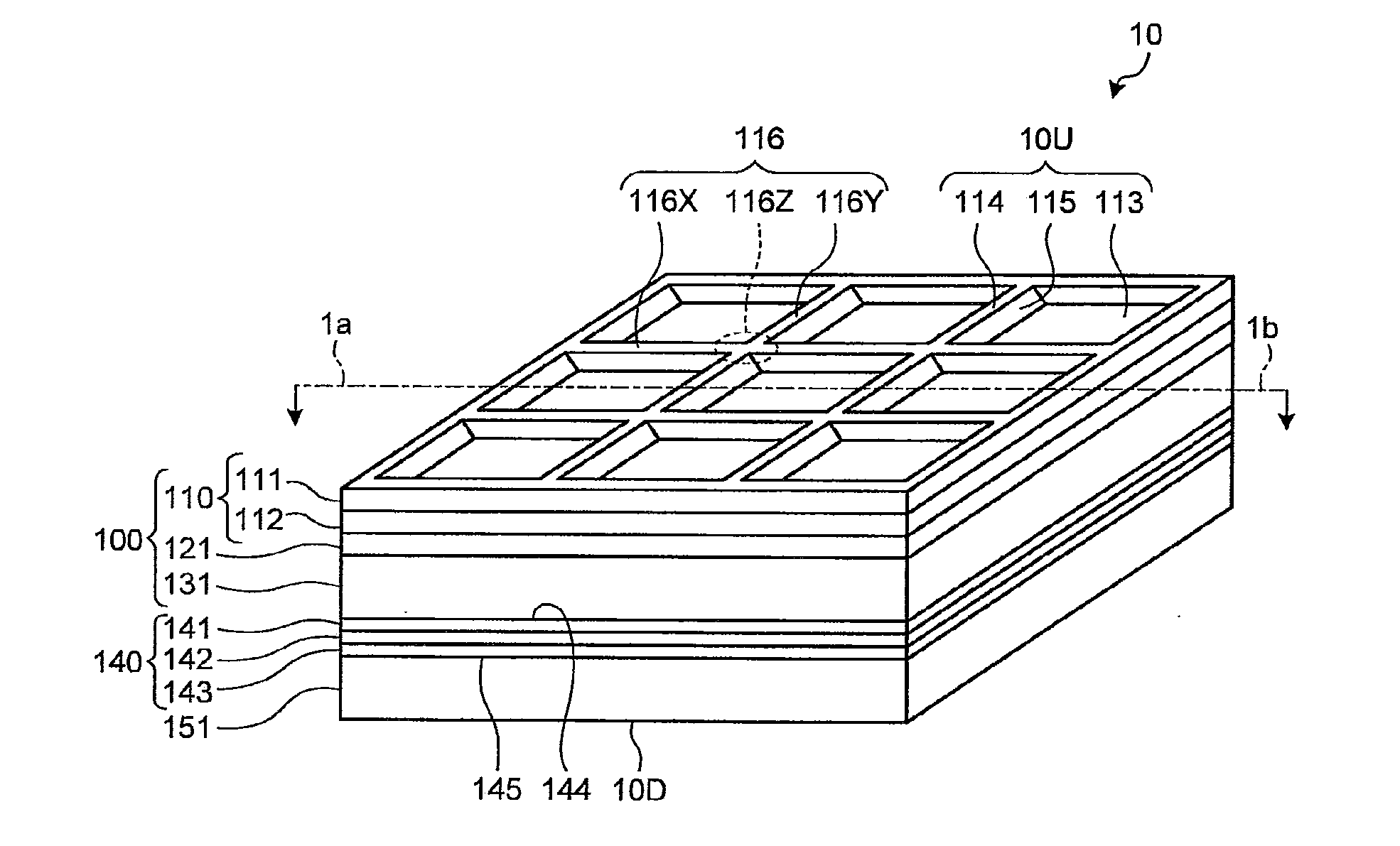
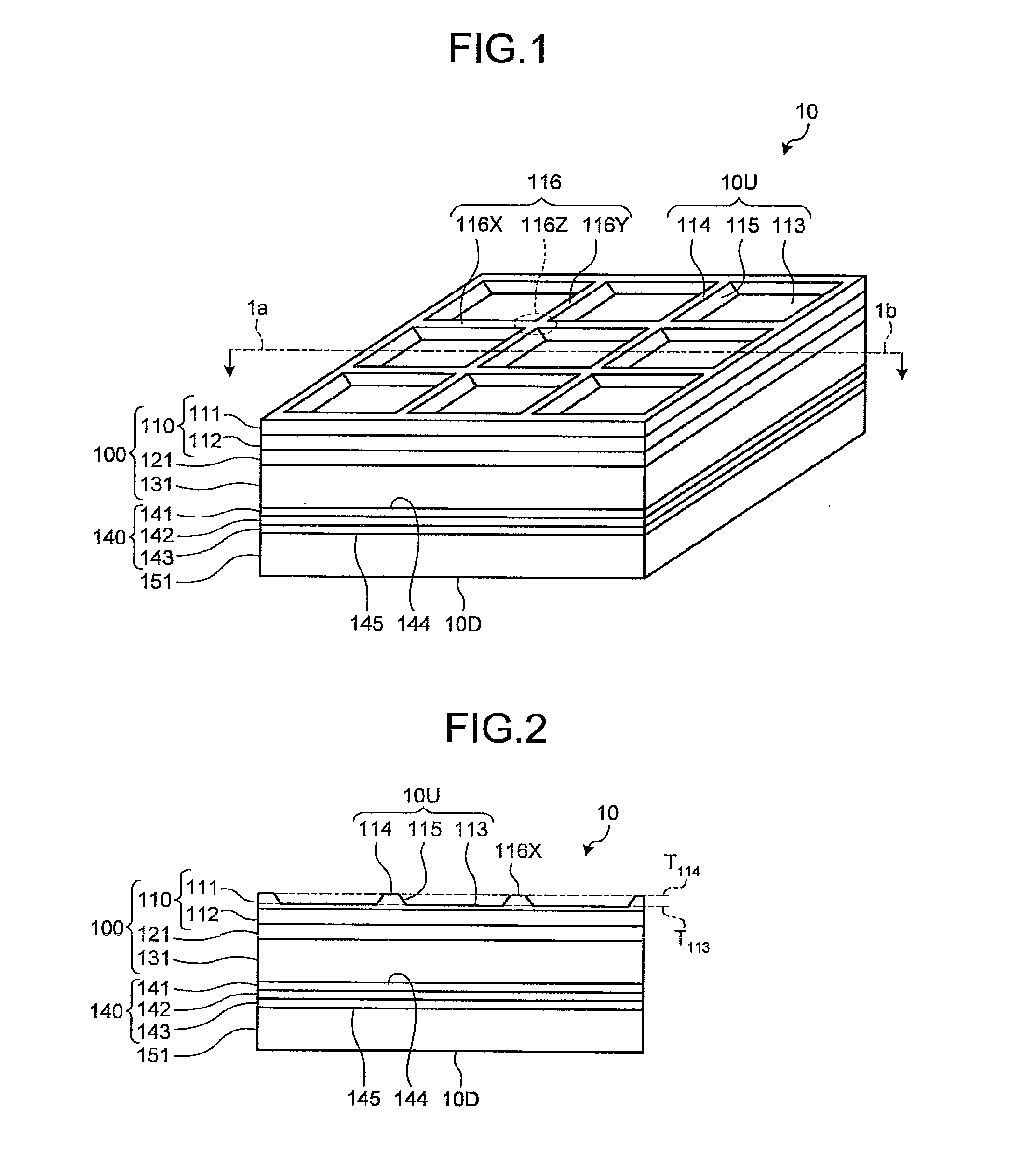
[0036]FIGS. 1 and 2 are each an explanatory view illustrating a light-emitting device according to a first embodiment of the present invention. FIG. 1 is a perspective view schematically illustrating the light-emitting device. FIG. 2 is a schematic cross-sectional view illustrating the light-emitting device of FIG. 1, the cross section being along a plane passing through line 1a-1b and perpendicular to a light output surface.
[0037]As shown in FIG. 1, the light-emitting device 10 according to the first embodiment of the present invention has a rectangular flat-shaped structure and includes an organic EL element 140 of a double-side emission type. The organic EL element 140 includes at least a first transparent electrode layer 141, a light-emitting layer 142, and a second transparent electrode layer 143 provided in this order. Light generated in the light-emitting layer 142 passes through the first electrode layer 141 or the second electrode layer 143, and then is e...
second embodiment
2. Second Embodiment
[0121]In the light output surface 10U according to the first embodiment, the levels T113 and T114 of the flat surface portions 113 and 114 in the thickness direction are each constant, and therefore, the difference between the levels T113 and T114 of the flat surface portion 113 and the flat surface portion 114 in the thickness direction is constant. However, in the light-emitting device of the present invention, for example, the flat surface portions may be provided at three or more different levels in the thickness direction, so that the differences between the levels of the flat surface portions in the thickness direction are nonuniform.
[0122]FIG. 8 is an enlarged view schematically illustrating an example of a cross section of a concavo-convex structure layer 910 on which flat surface portions 911, 912, and 913 are provided at three or more different levels T911, T912, and T913, respectively, in the thickness direction on a light output surface 910U. FIG. 8 i...
third embodiment
3. Third Embodiment
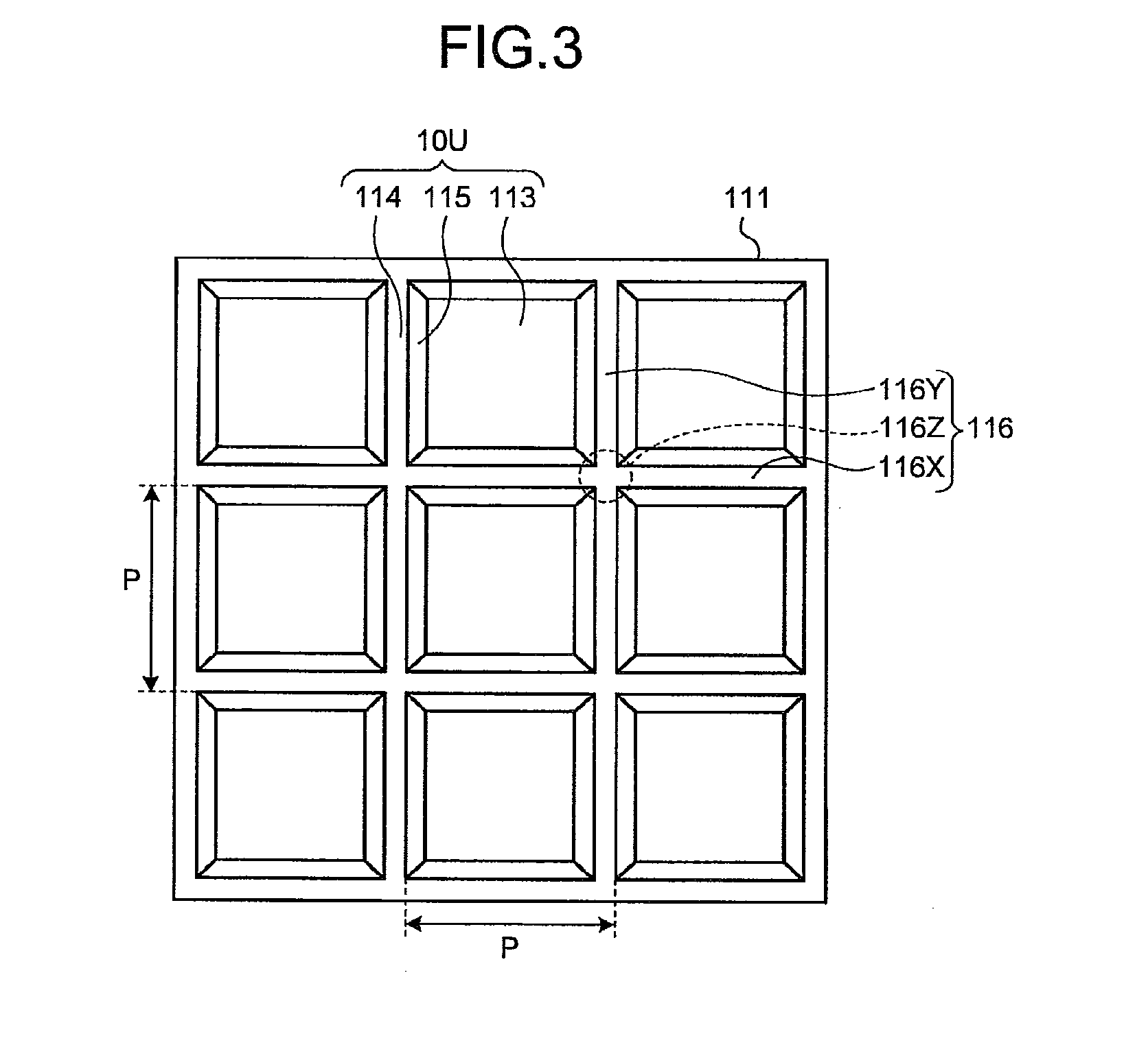
[0139]In the first and second embodiments, the convex portion 116 was configured to include the two groups of convex portions 116X and 116Y which extend in two directions perpendicular to each other; however, the convex portion 116 may also include only one group of convex portions extending in one direction or three or more groups of convex portions extending in three or more directions. Furthermore, the direction in which the convex portions extend may be arranged in a random fashion. Now, an example thereof will be described with reference to the drawing.
[0140]FIG. 10 is a perspective view schematically illustrating a light-emitting device according to a third embodiment of the present invention.
[0141]As shown in FIG. 10, the light-emitting device 30 according to the third embodiment of the present invention is the same as the light-emitting device 10 according to the first embodiment except that the device has a concavo-convex structure layer 311 in place of t...
PUM
 Abstract
Description
Claims
Application Information
 - R&D
- Intellectual Property
- Life Sciences
- Materials
- Tech Scout
- Unparalleled Data Quality
- Higher Quality Content
- 60% Fewer Hallucinations
Browse by: Latest US Patents, China's latest patents, Technical Efficacy Thesaurus, Application Domain, Technology Topic, Popular Technical Reports.
© 2025 PatSnap. All rights reserved.Legal|Privacy policy|Modern Slavery Act Transparency Statement|Sitemap|About US| Contact US: help@patsnap.com