
Conversion of Kinetic Into Electric Energy Utilizing The Universal Principles of Gravity & Magnetism

a technology of gravity & magnetism and conversion of kinetic energy into electric energy, applied in the direction of dynamo-electric components, dynamo-electric machines, electrical equipment, etc., can solve the problems of high cost of fossil fuels used in the generation of electricity for complex and expensive prior-art systems, and high cost of fossil fuels used in the generation of electricity for both commercial and home use, etc., to achieve reliable, inexpensive and uncomplicated manner

Inactive Publication Date: 2013-03-28
ZEAS JAMES T
View PDF7 Cites 0 Cited by
  • Summary
  • Abstract
  • Description
  • Claims
  • Application Information

AI Technical Summary

Benefits of technology

The present invention aims to create electricity from a clean, green source in a simple, affordable and effective way.

Problems solved by technology

It is well known that the present high-cost of fossil fuels used in the generation of electricity for both commercial and home use has necessitated the search for new and alternative sources of augmenting electricity-generation.
All of these prior-art systems require, and are based on, complicated and expensive technology.

Method used


Image

  • Conversion of Kinetic Into Electric Energy Utilizing The Universal Principles of Gravity & Magnetism
  • Conversion of Kinetic Into Electric Energy Utilizing The Universal Principles of Gravity & Magnetism
  • Conversion of Kinetic Into Electric Energy Utilizing The Universal Principles of Gravity & Magnetism

Examples


first embodiment

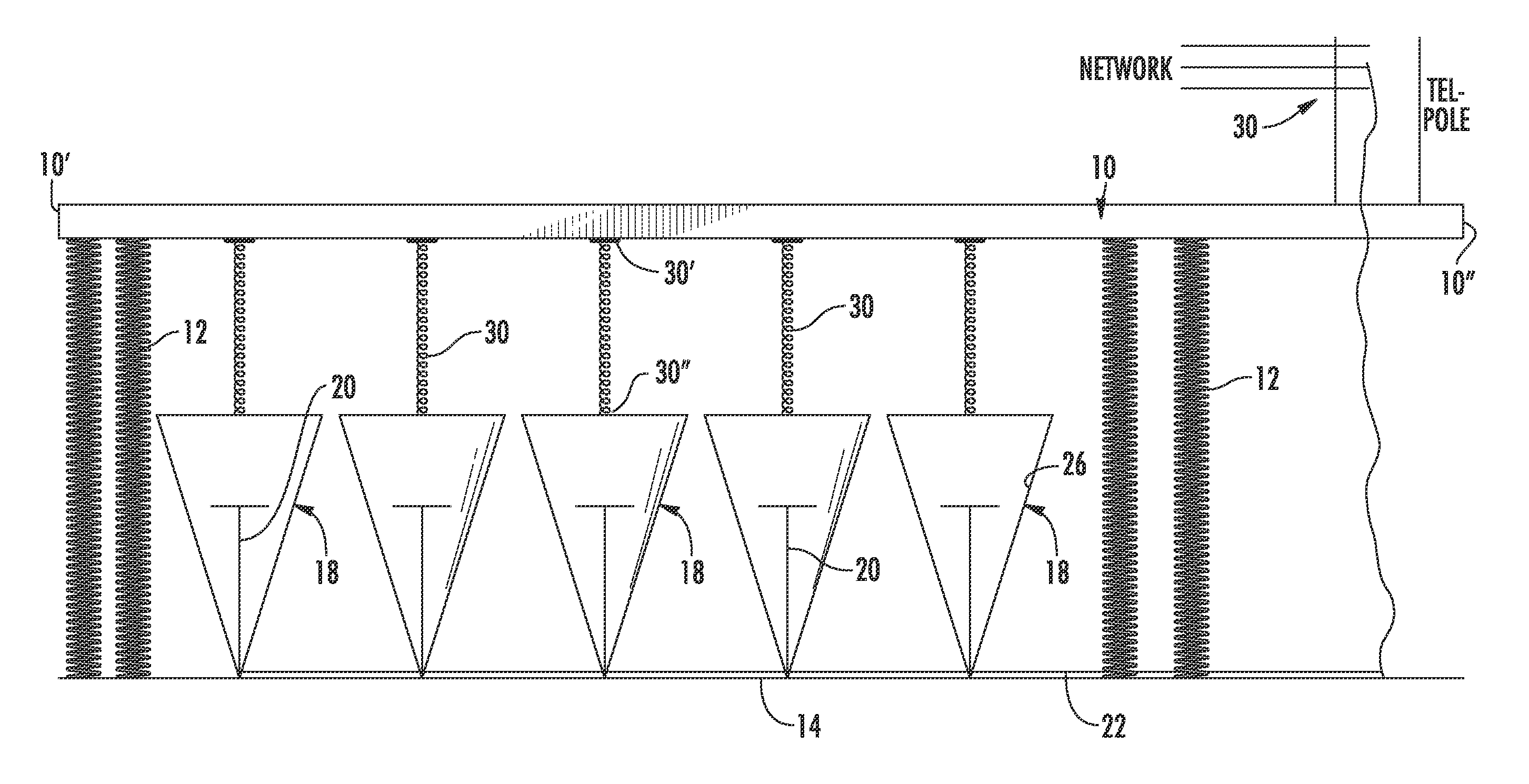
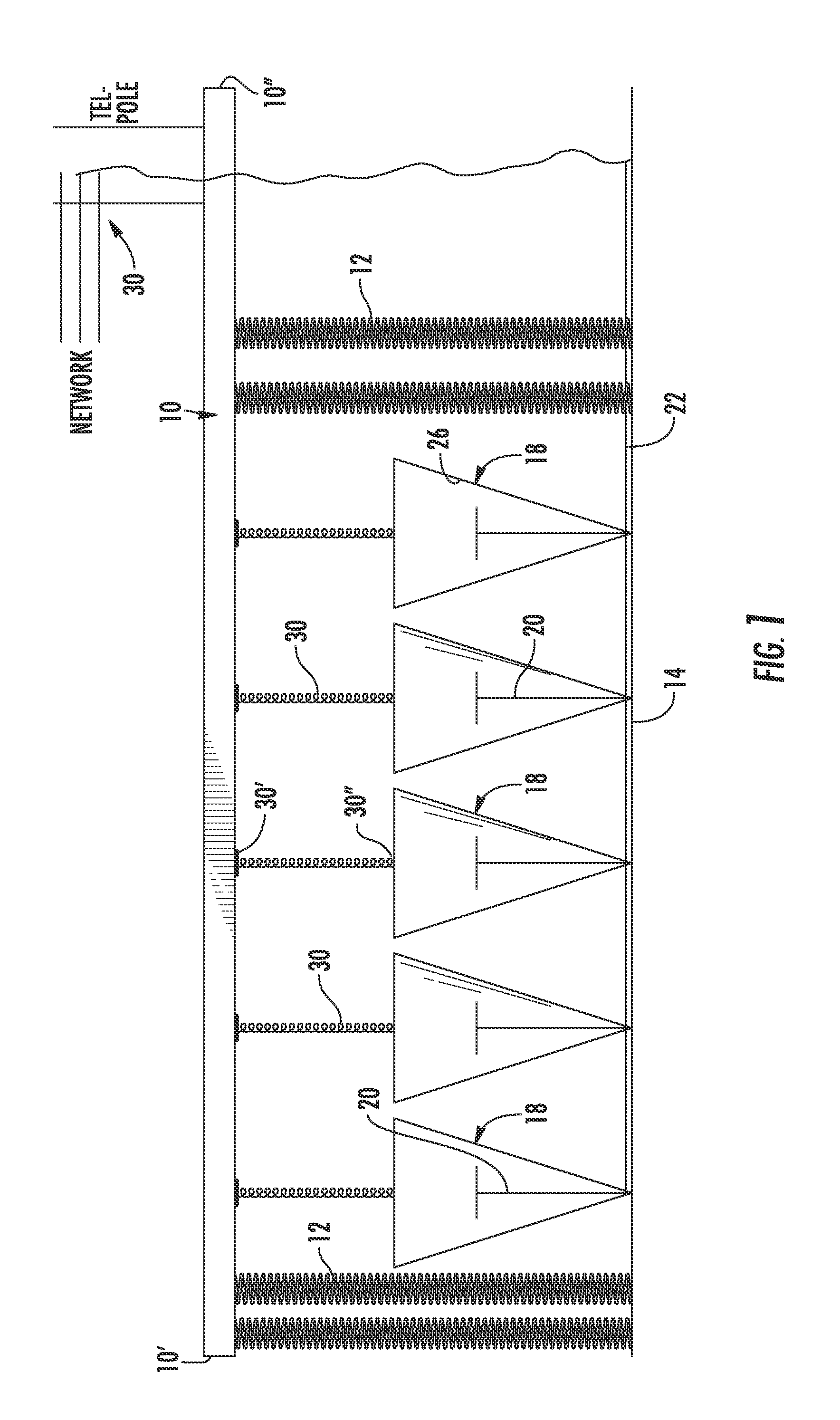
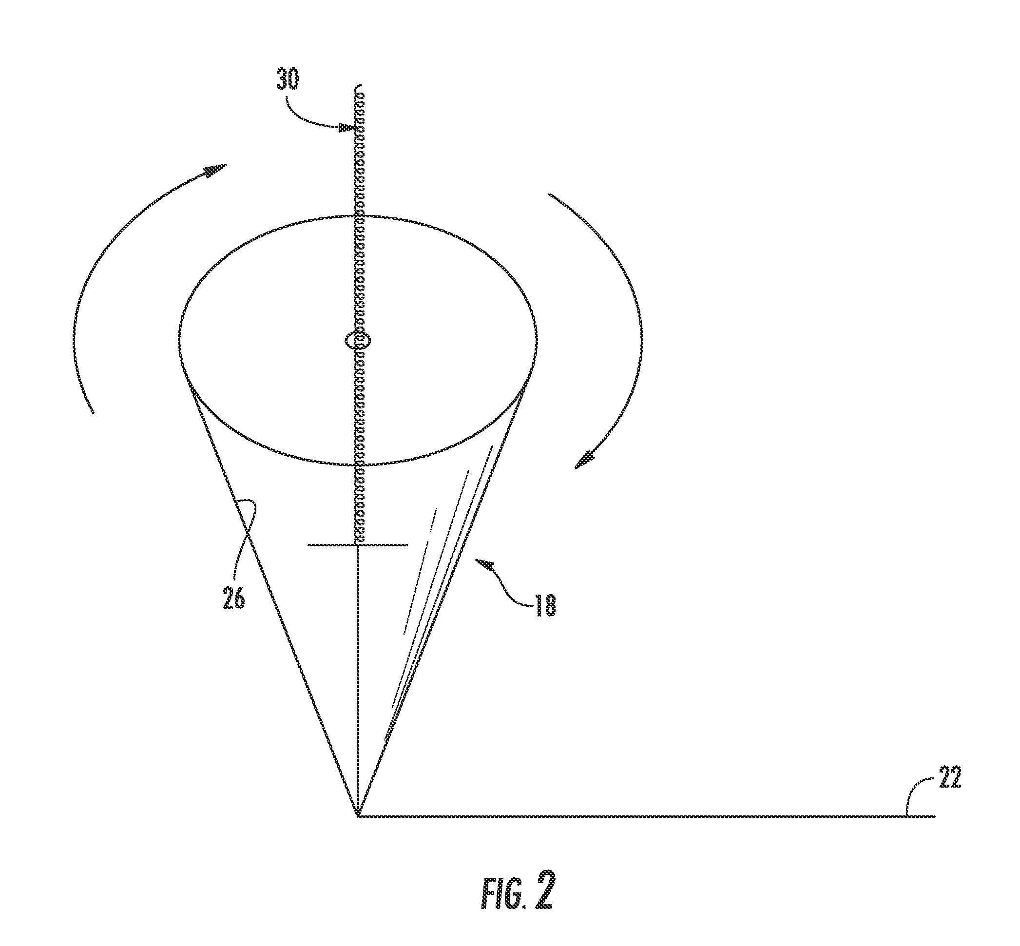
[0025]Referring now to the drawings in greater detail, and to FIGS. 1 and 2 for now, there is shown the first embodiment for generating electricity using the momentum of traveling, self-propelled vehicles over a road surface. The road surface in which the embodiment is employed is any highway or roadway containing one or more lanes. Floating or spring-based platforms 10 are constructed into the upper surface of the road, or highway, at downhill sections thereof in order to use gravity to offset the rolling friction between the tires of the vehicles and the platform, where each platform has a width approximately equal to the width of a lane across which it stretches. Each platform 10 may be flush with the remainder of the road surface at each end 10′, 10″, or may be slightly raised thereabove, in which case each end 10′, 10″ would be connected to a sloping transitional section that gradually transitions the passing vehicles for passing over the platform. Each platform 10 is spring-bi...

second embodiment

[0030]In a modification of FIGS. 3-8, instead of the use of the rollers 40, spinning or rotating cylinders 50 may be used, as shown in FIG. 9, with each cylinder having a length that substantially extends across the width of a lane of the roadway. Each cylinder 50 has an interiorly-embedded, electrically conducting copper wire or wires 52 which extend longitudinally axially in the interior thereof, through the stationary mounting shaft (not shown), with the ends 52′, 52″ thereof being output to a collective line coupling all of the interiorly-embedded, electrically conducting metal wires 52 together, for transmitting the electricity generated to a power grid or the battery-storage system, as explained above. As in the case of the rollers 40, each cylinder 50 is provided with interiorly-embedded, circumferential or annular magnets or magnetic material, or is made of composite material including magnetic properties so that. As the cylinders 50 rotate via contact with the tires of the ...


PUM


Abstract

The present invention is directed to a method of generating electricity from the rolling contact between the wheels of self-propelled vehicles, and the support surfaces, upon which the self-propelled vehicles translate. Platforms over which the tires of the moving vehicles pass are implanted into a road surface. Mounted below the platforms are a series of rotatable cones each of which mounts therein a plurality of electrically-conducting wires, or equivalents. Surrounding each rotatable cone is a magnetic-field producing element. Each rotating cone is connected to a portion of the platforms. As the vehicles pass over the platform, each platform is moved vertically downward, causing the each respective cone to rotate, thus creating a magnetic flux that produces electricity in the copper wires mounted within each cone.

Description

BACKGROUND OF THE INVENTION[0001]The present invention is directed to a method of generating electricity from the rolling contact between the wheels or tires of self-propelled vehicles and the support surface upon which the self-propelled vehicles translate.[0002]It is well known that the present high-cost of fossil fuels used in the generation of electricity for both commercial and home use has necessitated the search for new and alternative sources of augmenting electricity-generation. These so-called “clean” or “green” sources, such as wind power, solar power, fuel cells, thermal electric generation (i.e., harnessing the heat of volcanoes and the earth's magma along shallow fault lines), hydroelectricity, harnessing landfill, human waste and other gases, and the like, have been developed to a degree where they are now in common usage across the globe. The present invention is also directed to such a clean source for generating electricity, which may be used to substitute or suppl...

Claims


Application Information

Patent Timeline
Patent Type & Authority Applications(United States)
IPC IPC(8): H02K7/18
CPCH02K7/1853
Inventor ZEAS, JAMES T.
Owner ZEAS JAMES T
Features
  • Generate Ideas
  • Intellectual Property
  • Life Sciences
  • Materials
  • Tech Scout
  • Unparalleled Data Quality
  • Higher Quality Content
  • 60% Fewer Hallucinations
Learn More