Image Forming Apparatus

a technology resin frame, which is applied in the direction of electrographic process apparatus, instruments, optics, etc., can solve the problems of metal frame increasing the manufacturing cost and weight of image forming apparatus, resin frame may not provide substantial rigidity to hold image forming unit, and distortion of resin frame at intermediate areas may not be avoided, so as to achieve substantial rigidity, enhance structure, and avoid distortion of resin fram

Active Publication Date: 2013-03-28
BROTHER KOGYO KK
View PDF6 Cites 20 Cited by
  • Summary
  • Abstract
  • Description
  • Claims
  • Application Information

AI Technical Summary

Benefits of technology

[0007]Even with the metal bars bridged between the resin frames, however, distortion of the resin frames still may not be avoided at intermediate areas between coupled areas, in which the coupling bars are directly attached to the resin frames. In other words, substantial rigidity may not be provided by the resin frames with the coupling bars. Substantial rigidity may be achieved if a piece of resin plate to cover an entire plane of each resin frame may be attached to the resin frames; however, such enhancing structure may increase manufacturing cost and weight of the image forming apparatus.
[0008]In view of the difficulty, the present invention is advantageous in that an image forming apparatus having a pair of resin frames, which support at least a part of an image forming unit at laterally opposite sides, is provided whilst rigidity of an entire frame assembly of the image forming apparatus, including the resin frames, is maintained and an amount of metal to be used in the frame assembly is minimized.

Problems solved by technology

The metal frames may often increase manufacturing cost and weight of the image forming apparatus.
However, the resin frames may not provide substantial rigidity to hold the image forming unit but may be more deformable to external force than the metal frames.
Even with the metal bars bridged between the resin frames, however, distortion of the resin frames still may not be avoided at intermediate areas between coupled areas, in which the coupling bars are directly attached to the resin frames.
In other words, substantial rigidity may not be provided by the resin frames with the coupling bars.
Substantial rigidity may be achieved if a piece of resin plate to cover an entire plane of each resin frame may be attached to the resin frames; however, such enhancing structure may increase manufacturing cost and weight of the image forming apparatus.

Method used


Image

  • Image Forming Apparatus
  • Image Forming Apparatus
  • Image Forming Apparatus

Examples


Embodiment Construction

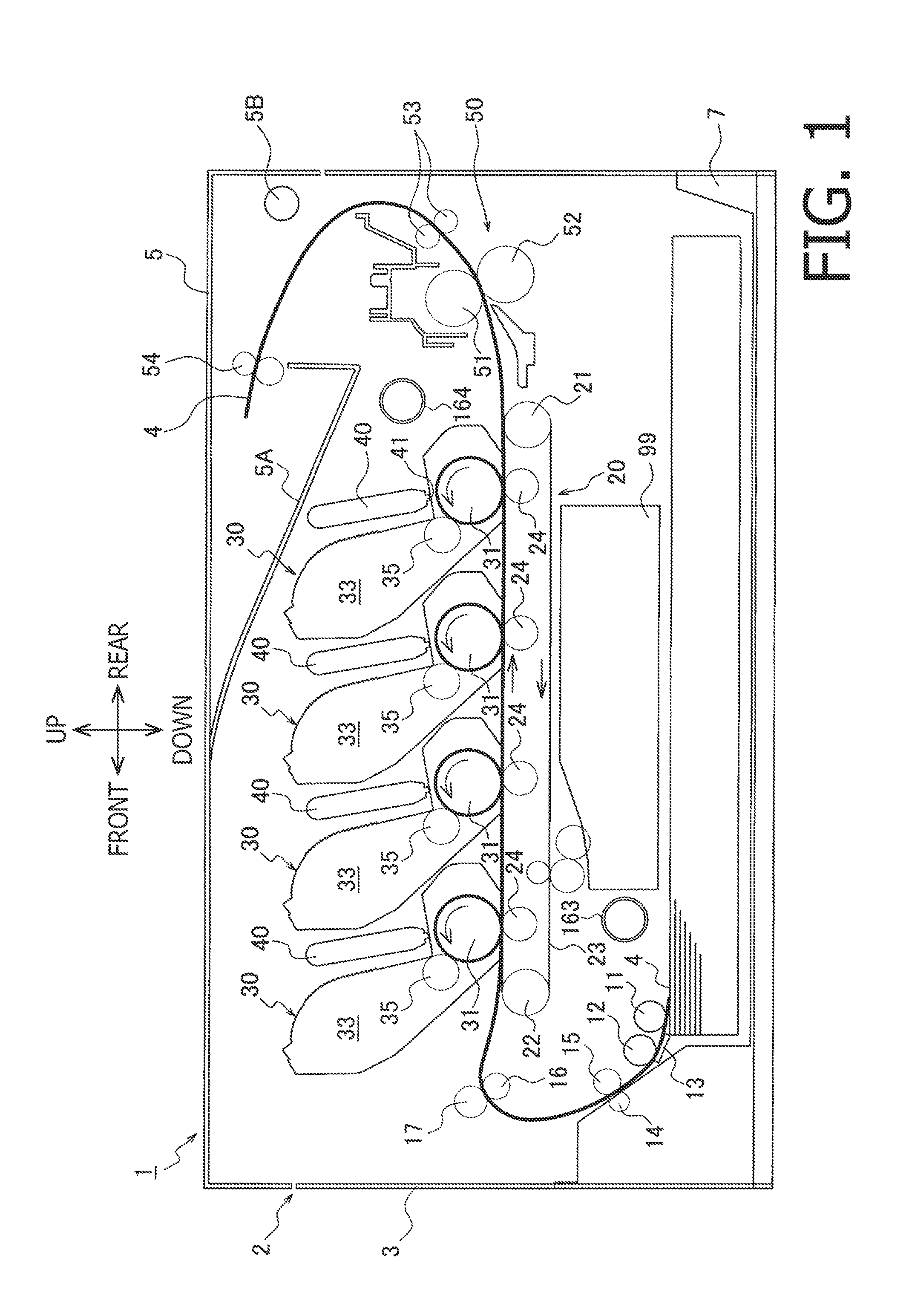
[0015]Hereinafter, an embodiment according to an aspect of the present invention will be described with reference to the accompanying drawings. FIG. 1 is a cross-sectional side view of an image forming apparatus 1 according to an embodiment of the present invention. In the following description, directions concerning the image forming apparatus 1 will be referred to based on the orientation indicated by arrows shown in each drawing. For example, a viewer's left-hand side in FIG. 1 is referred to as front for the image forming apparatus 1, and a viewer's nearer side will is referred to as right.

Overall Configuration of the Image Forming Apparatus

[0016]The image forming apparatus 1 is a color printer capable of forming multi-colored images on a sheet 4 being a recording medium in a direct-transfer tandem method as the sheet 4 is carried in a sheet-conveyer path along a sheet-conveying direction. The sheet-conveying direction, which therefore coincides with the sheet-conveyer path, is ...


PUM


Abstract

An image forming apparatus, including an image forming unit configured to form an image on a recording medium, a pair of resin frames configured to support the image forming unit at least partially from mutually opposite sides, a pair of metal-made upper enhancing pieces arranged along upper faces of the resin frames, and a pair of first metal beams, each of which is arranged to bridge over a position between the paired upper enhancing pieces and forms a four-sided opening in conjunction with each other and with the paired upper enhancing pieces, is provided.

Description

CROSS REFERENCE TO RELATED APPLICATION[0001]This application claims priority from Japanese Patent Application No. 2011-212988, filed on Sep. 28, 2011, the entire subject matter of which is incorporated herein by reference.BACKGROUND[0002]1. Technical Field[0003]An aspect of the present invention relates to an image forming apparatus with an image forming unit for forming an image on a recording medium. More specifically, the present invention relates to an image forming apparatus including a pair of resin frames to support at least a part of the image forming unit at laterally opposite sides.[0004]2. Related Art[0005]An image forming apparatus for forming an image on a recording medium in an electro-photographic method may often have a pair of metal frames (e.g., steel plates), which support an image forming unit at laterally opposite sides (e.g., right and left sides). The metal frames may often increase manufacturing cost and weight of the image forming apparatus. Therefore, the m...

Claims


Application Information

Patent Timeline
Patent Type & Authority Applications(United States)
IPC IPC(8): G03G15/00
CPCG03G21/1619
Inventor NAKASHIMA, ATSUHISA
Owner BROTHER KOGYO KK
Why Eureka
Try Eureka