Machine vise parallel with angled edges

a technology of angled edges and machine vises, applied in the field of parallel or support, can solve the problems of large volume, difficult adjustment, and waste of time between set ups, and achieve the effect of saving a great amount of time and low profile design

Inactive Publication Date: 2013-04-11
KURT MANUFACTURING COMPANY INC
View PDF6 Cites 8 Cited by
  • Summary
  • Abstract
  • Description
  • Claims
  • Application Information

AI Technical Summary

Benefits of technology

[0007]The angled parallel can be used to locate parts vertically for working on the ends of the part, and can also function as a work stop on the vise jaw. Its low profile design and the ability to install it in just moments saves a great amount of time between set ups. The easily mounted angled parallel replaces the need for bulky, hard to adjust work stops.

Problems solved by technology

Its low profile design and the ability to install it in just moments saves a great amount of time between set ups.
The easily mounted angled parallel replaces the need for bulky, hard to adjust work stops.

Method used


Image

  • Machine vise parallel with angled edges
  • Machine vise parallel with angled edges
  • Machine vise parallel with angled edges

Examples


Embodiment Construction

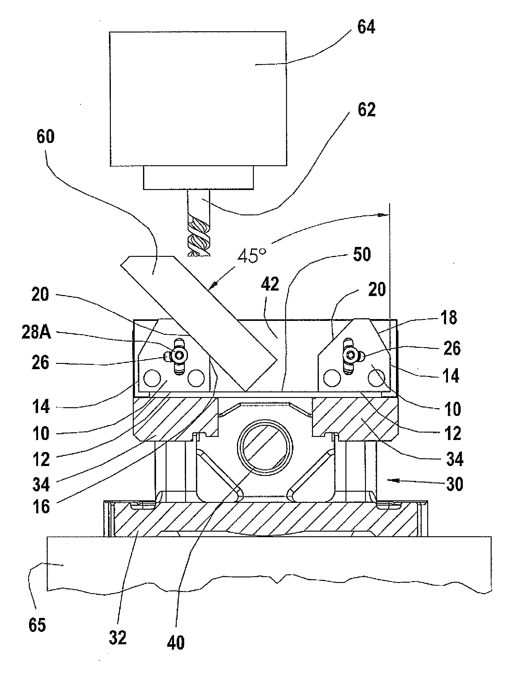
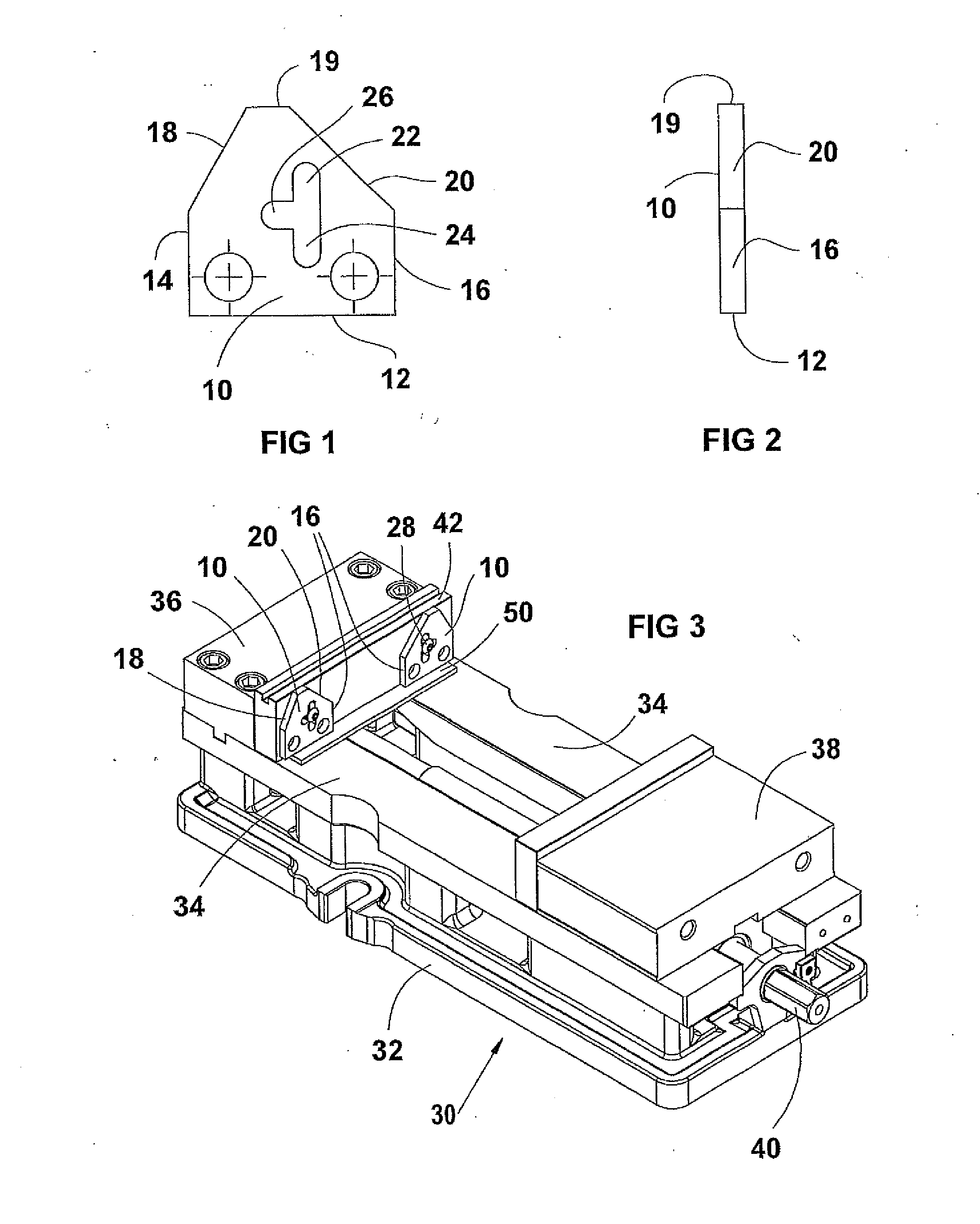
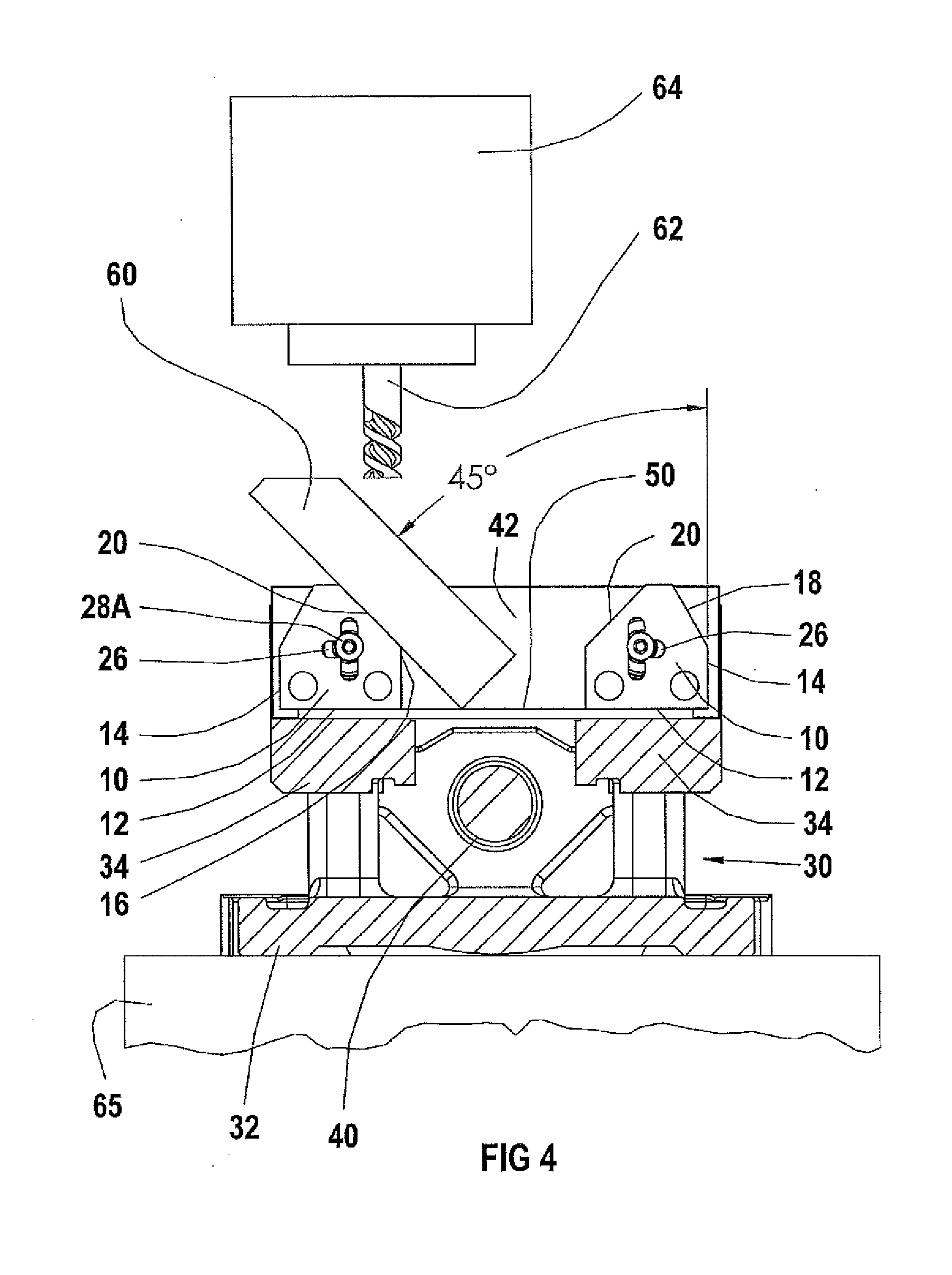
[0016]FIGS. 1 and 2 show an angled parallel or work piece orienting plate 10 made according to the present disclosure which is a small, flat metal plate portion or section that as shown is machined to have three reference straight edges including a first or base reference edge 12, and second and third side reference edges 14 and 16 that are spaced apart and precisely perpendicular (at 90 degrees) to the first or base reference edge 12. The reference edges define a width of the angled parallel.

[0017]The angled parallel 10 further has an angled support edge 18 machined at an angle of 30 degrees relative to the second reference side edge 14, or at an angle of 60 degrees relative to the base reference edge 12. Edge 18 intersects the side edge 14 at a location spaced upwardly from the base reference edge 12 and extends toward the center of the vise parallel and in direction away from reference edge 12. A second angled edge 20 is machined at a 45 degree angle relative to the third referen...


PUM


Abstract

A work orienting plate or angled vise parallel for use with a machine vise and which angled plate has first, second and third reference edges with the second and third reference edges being spaced apart side edges that are perpendicular to the first edge. Angled work piece support edges join the second and third reference edges, respectively. The angled work piece support edges are at different angles from one another so that a work piece can be supported on any one of the edges relative to a reference surface of a vise on which the work orienting plate is mounted to position the work piece at selected angles for machining angled surfaces.

Description

BACKGROUND OF THE DISCLOSURE[0001]The present disclosure relates to a vise parallel or support for positioning a work piece in a vise or similar clamping device at precisely set angles selectable by the user to provide a quickly changed support to hold and orient a work piece at a selected one of a plurality of preset angles.[0002]In the prior art, various sine bars or sine blocks have been used for precisely setting angles for work pieces held in a vise or clamp. Sine bars are usually provided with a support of precise length, and by inserting precision gauge blocks under the supports, the precise angle of the flat surface of the sine bar can be set using known geometry principals. The height of the gauge blocks needed to achieve a desired angle is generally determined from a machinist handbook, which has a set of tables giving dimensions for setting the angle of a bar of known length, usually five inches.[0003]It has been found that for the majority of parts that are to be machine...

Claims


Application Information

Patent Timeline
Patent Type & Authority Applications(United States)
IPC IPC(8): B25B1/24B23Q3/04
CPCB25B1/2463B25B1/2457
Inventor SCHMIDT, DAVID L.
Owner KURT MANUFACTURING COMPANY INC
Why Eureka
Try Eureka