Image data processing apparatus

a technology of image data and processing apparatus, which is applied in the field of image data processing apparatus, can solve the problems of inability to achieve the rate required for barcode analysis processing, increase the amount of data which must be output, and degradation of barcode analysis accuracy, so as to increase the amount of image data to be output from the imaging apparatus 1 and the effect of increasing the amount of tim

Active Publication Date: 2006-01-19
SEMICON COMPONENTS IND LLC
View PDF10 Cites 3 Cited by
  • Summary
  • Abstract
  • Description
  • Claims
  • Application Information

AI Technical Summary

Benefits of technology

[0010] For example, because barcode analysis processing generally requires multiple screens of image information, the output frame rate from the imaging apparatus must be set to approximately 30 fps (frames per second). However, when a large amount of data is output from the imaging apparatus as the image data for one screen, a much greater amount of time is required for data transfer. As such, the frame rate required for barcode analysis processing cannot be attained, disadvantageously resulting in degradation of the accuracy of barcode analysis.
[0011] When, within the barcode reader system, an additional function is to be executed on the system microcomputer side to perform an image processing for a special effect, an image data for a still image comprising (luminance data in the form of 8 bits×640×480)+(chrominance data in the form of 8 bits×640×480) is required for the image processing. For this purpose, the amount of the image data to be output from the imaging apparatus 1 becomes further increased. As such, it becomes increasingly difficult to appropriately supply the amount of image data required by the respective functions.

Problems solved by technology

When two different types of image data must be included in the image data supplied from the imaging apparatus, the amount of data which must be output increases, leading to various problems, such as those described below.
However, when a large amount of data is output from the imaging apparatus as the image data for one screen, a much greater amount of time is required for data transfer.
As such, the frame rate required for barcode analysis processing cannot be attained, disadvantageously resulting in degradation of the accuracy of barcode analysis.
As such, it becomes increasingly difficult to appropriately supply the amount of image data required by the respective functions.
The above-noted problems are found not only in barcode reader systems and image processing systems, but generally exist commonly in any systems in which image data are output from an imaging apparatus to a plurality of external apparatuses which require different amounts of data or data processed in different manners of image processing.

Method used


Image

  • Image data processing apparatus
  • Image data processing apparatus
  • Image data processing apparatus

Examples


first embodiment

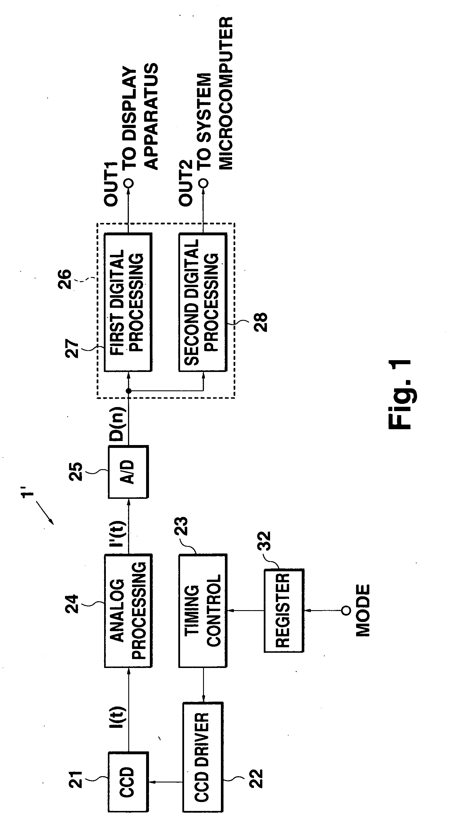
[0026]FIG. 1 is a block diagram showing the configuration of the present invention. In FIG. 1, similarly as in FIG. 11, a system microcomputer 3 for executing barcode analysis processing and a display apparatus 2 for displaying a reproduced image are shown as example external apparatuses, and an imaging apparatus for use in a barcode reader system including those components is employed as an example for describing the present invention.

[0027] The imaging apparatus 1′ shown in FIG. 1 includes a CCD image sensor 21, CCD driver 22, timing control circuit 23, register 32, analog processing circuit 24, A / D converter circuit 25, and digital processing circuit 26.

[0028] The CCD image sensor 21 comprises a light-receiving section including a plurality of light-receiving pixels arranged in an array, for accumulating information charges in accordance with an object image. The CCD image sensor 21 further comprises a transfer section for sequentially transferring, in units of one line, the inf...

second embodiment

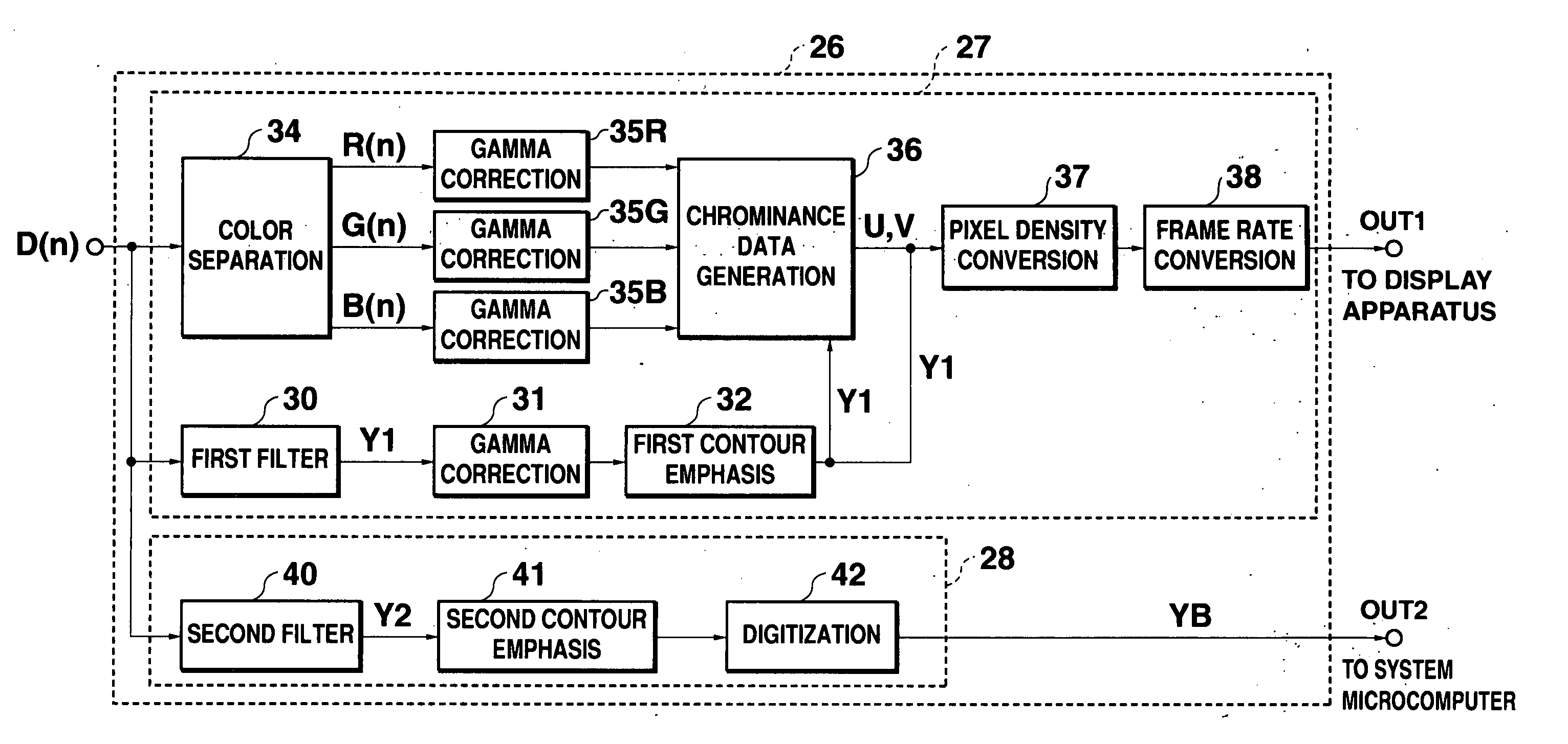
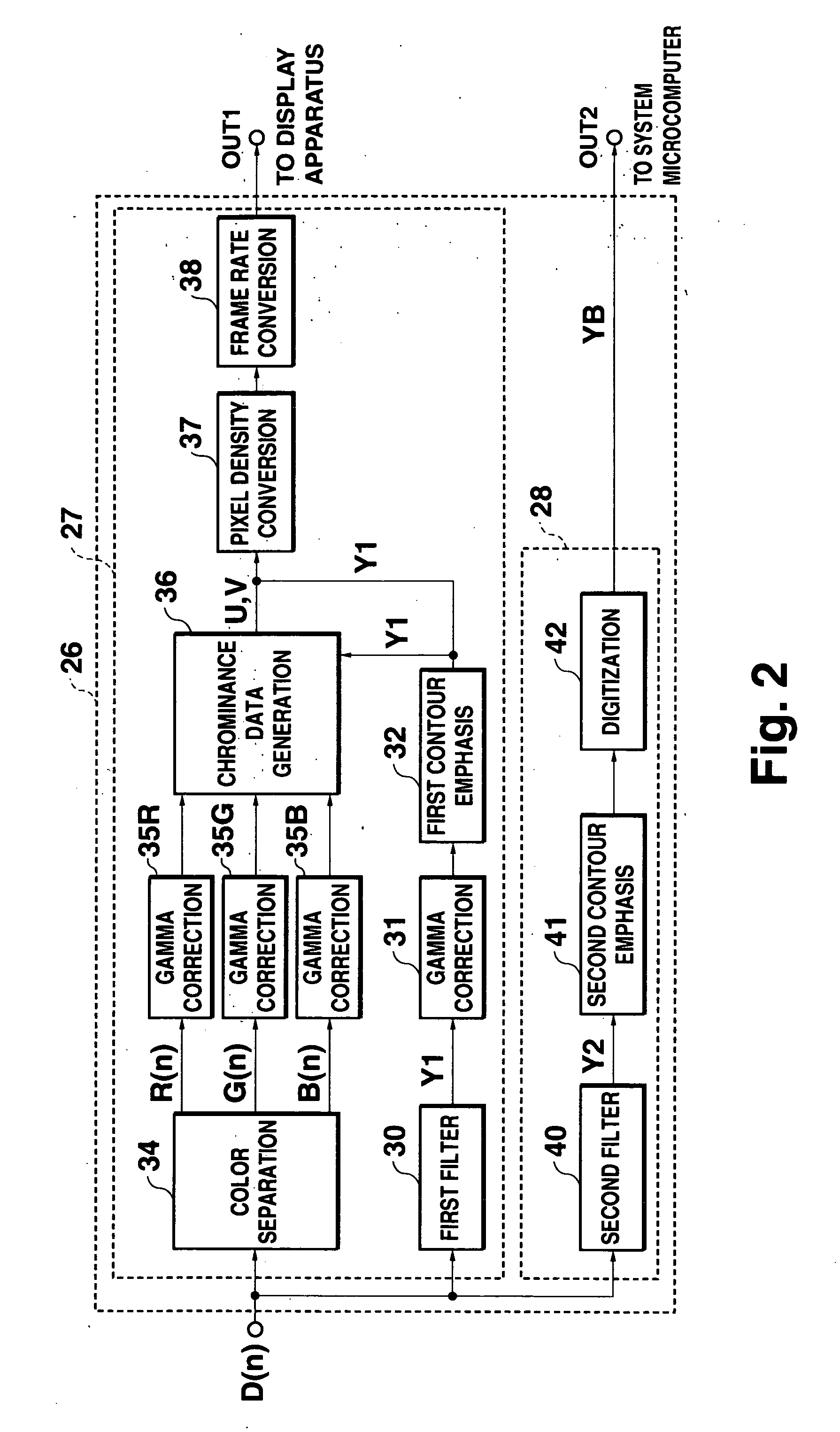
[0053]FIG. 7 is a block diagram showing the configuration of the digital processing circuit 26 of the In FIG. 7, elements that are identical to those in FIG. 2 are labeled with the same reference numerals, and explanation of those elements will not be repeated.

[0054] After the 8-bit data composed of the first luminance data Y1 or the chrominance data U or V has been subjected to frame rate conversion in the frame rate conversion circuit 38, the synthesizing circuit 70 acquires data of the four high-order bits of the 8-bit data and data of the four low-order bits of the 8-bit data. The synthesizing circuit 70 also acquires the 1-bit digitized data YB. The synthesizing circuit 70 synthesizes the acquired data, and outputs the synthesized data as the output data D(o). The synthesizing circuit 70 comprises a selector 71, and, among the three input data sets, the data of the four low-order bits of the first luminance data Y1 or the chrominance data U, V, and the digitized data YB are re...


PUM


Abstract

A first processing circuit subjects image data output from an A/D converter circuit to a first signal process to produce first image data. A second processing circuit subjects image data to a second signal process, which is independent of the first signal process, to produce second image data. The first and second processing circuits execute the first and second signal processes in a parallel manner to output the first and second image data to a display device and a system microcomputer.

Description

TECHNICAL FIELD [0001] The present invention relates to an image data processing apparatus for performing a predetermined signal processing on input image data and generating an output data for supplying to an external apparatus. BACKGROUND ART [0002] In a conventional system, image data are output from an imaging apparatus to a plurality of external apparatuses, and the external apparatuses perform various types of signal processing such as image processing for display, analysis, and special effects. According to an example processing for display, image data conforming to a standard format is output from an imaging apparatus, and reductions in pixel density and gradation of the image data are performed on the display apparatus side so as to convert the pixel density and gradation into a format that can be displayed on a display panel. For example, in an example an a lysis processing, image data may first be obtained by scanning a barcode to read a pattern of black and white stripes...

Claims


Application Information

Patent Timeline
Patent Type & Authority Applications(United States)
IPC IPC(8): H04N5/228G06T5/20G06T1/00H04N1/409
CPCG06T1/00H04N1/40H04N1/46
Inventor WATANABE, TOHRU
Owner SEMICON COMPONENTS IND LLC
Why Eureka
Try Eureka