Pitch system for a wind energy system and method for operating a pitch system

a technology of wind energy system and pitch system, which is applied in the direction of electric generator control, machines/engines, mechanical equipment, etc., can solve the problems of affecting the operation efficiency of the system, and requiring relatively expensive electrical test circuits

Inactive Publication Date: 2013-04-11
SIEMENS AG
View PDF6 Cites 12 Cited by
  • Summary
  • Abstract
  • Description
  • Claims
  • Application Information

AI Technical Summary

Benefits of technology

[0025]According to another advantageous feature of the present invention, the emergency energy store may be discharged only partially, so that an emergency maneuver is always possible. Then, the method can also be carried out for all the blades simultaneously.
[0026]A further aspect of the present invention relates to a pitch system for setting a pitch angle of at least one rotor blade of a wind energy system. The pitch system has at least one actuating device for setting a pitch angle of at least one rotor blade. The pitch system can receive electrical energy via a supply connection from an (external) electrical supply network. An emergency energy store of the pitch system is configured in order to operate at least one of the actuating devices in the event that the supply network fails. A control device of the pitch system is configured to operate the pitch system according to an embodiment of the inventive method. The pitch system according to the invention has the advantage that the emergency energy store for the actuating devices can also be tested in a normal operating mode of the wind energy system.

Problems solved by technology

These age over their operating life and thereby lose capacitance.
A disadvantage of the conventional solutions is that, for testing an emergency energy store, relatively expensive electrical test circuits are needed and the testing takes time, during which the wind energy system cannot be used for generating electrical energy.

Method used


Image

  • Pitch system for a wind energy system and method for operating a pitch system
  • Pitch system for a wind energy system and method for operating a pitch system
  • Pitch system for a wind energy system and method for operating a pitch system

Examples


Embodiment Construction

[0032]Throughout all the figures, same or corresponding elements may generally be indicated by same reference numerals. These depicted embodiments are to be understood as illustrative of the invention and not as limiting in any way. It should also be understood that the figures are not necessarily to scale and that the embodiments are sometimes illustrated by graphic symbols, phantom lines, diagrammatic representations and fragmentary views. In certain instances, details which are not necessary for an understanding of the present invention or which render other details difficult to perceive may have been omitted.

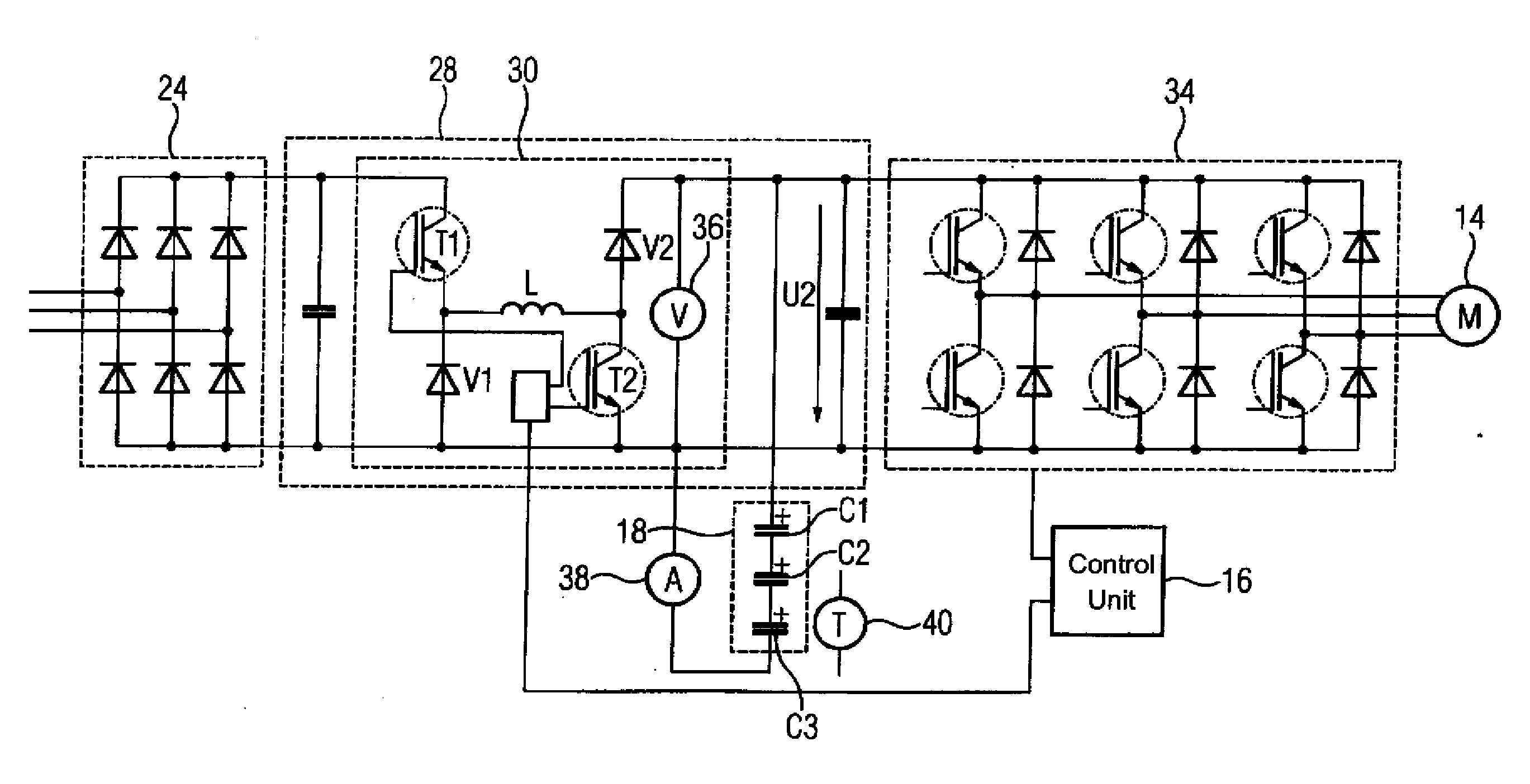
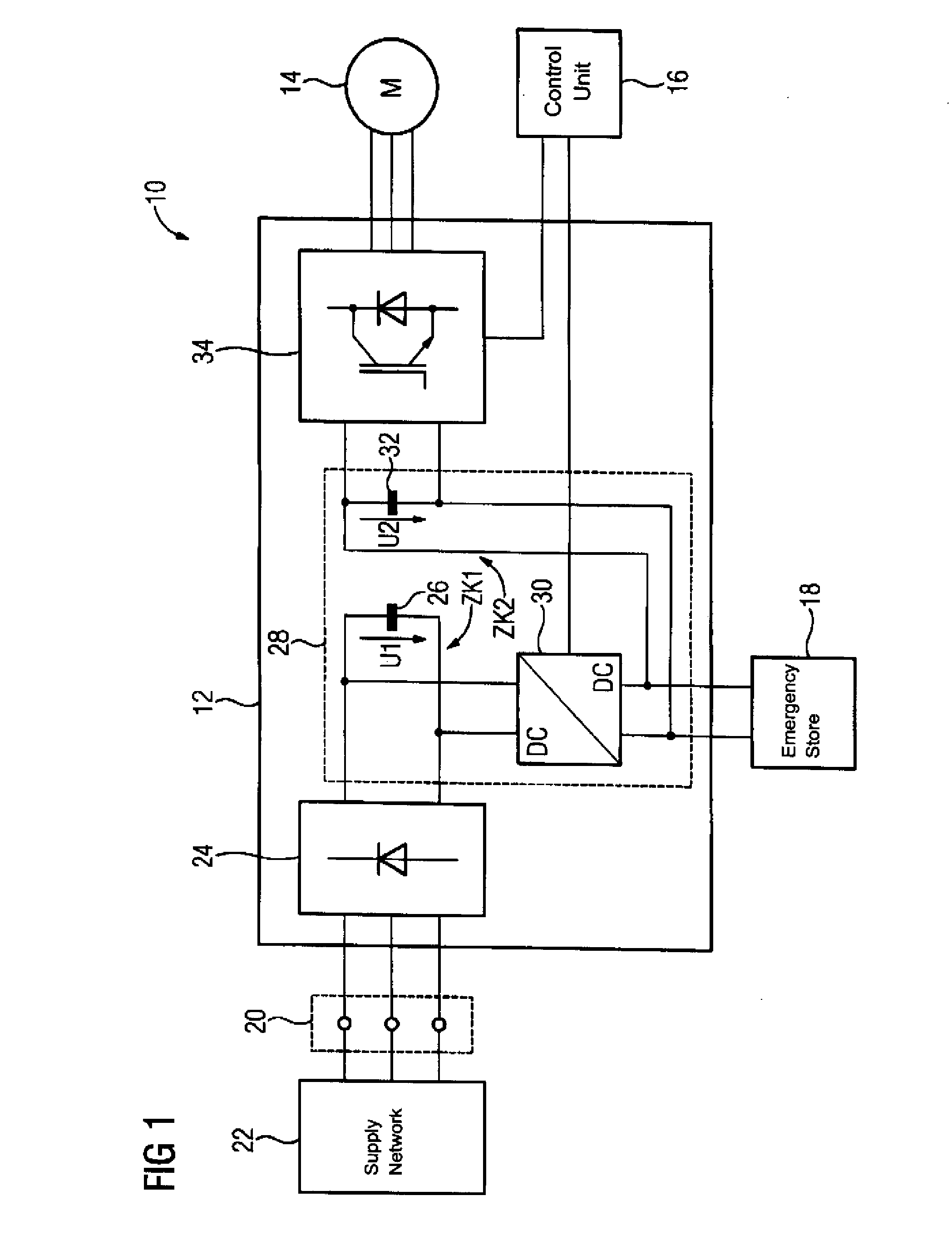
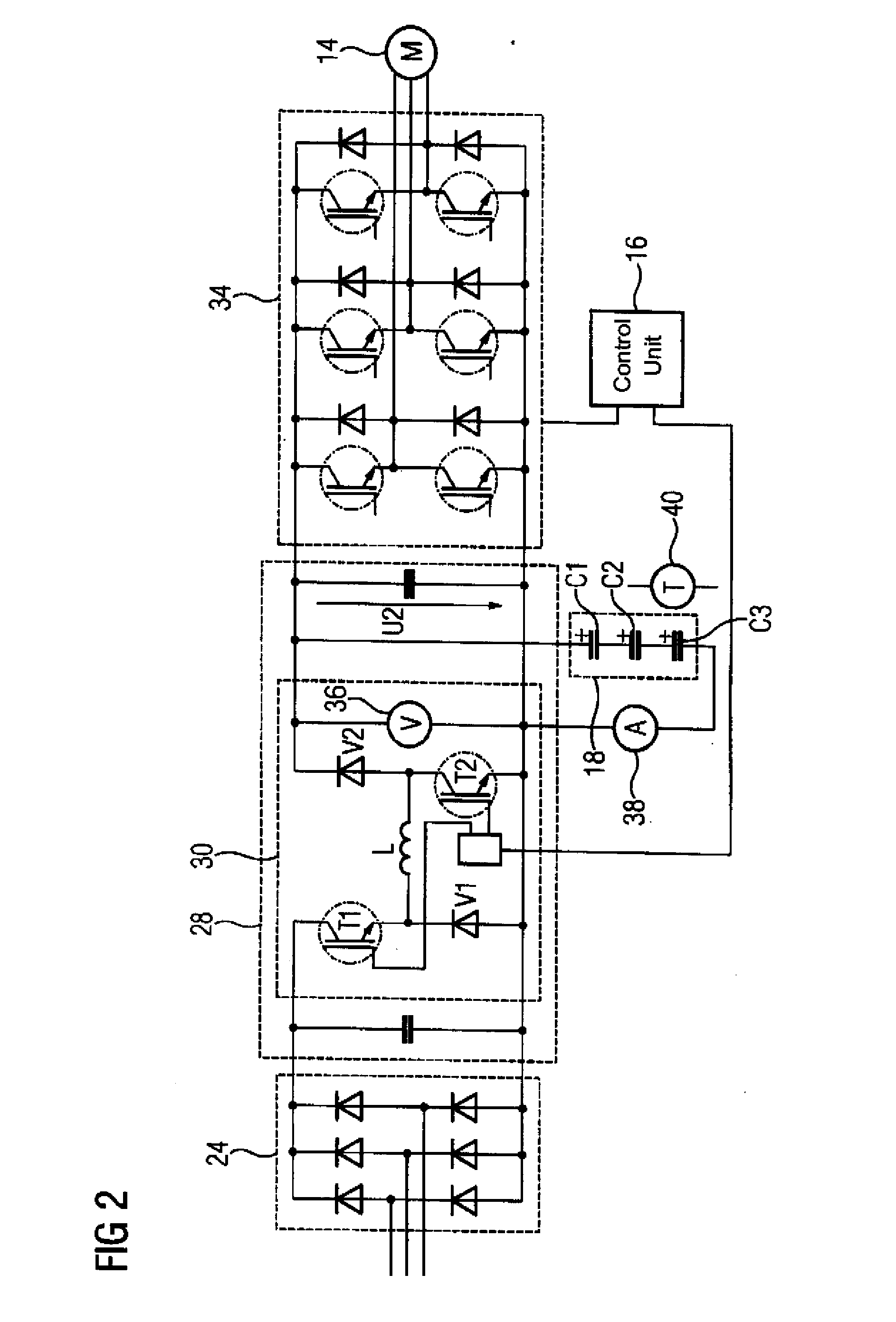
[0033]Turning now to the drawing, and in particular to FIG. 1, there is shown a blade adjustment system or actuating system 10 which is installed in a wind energy system. By means of the actuating system 10, pitch angles of rotor blades (not shown) of a rotor of the wind energy system can be set. In FIG. 1 only components of the actuating system 10, by means of which just on...


PUM


Abstract

A pitch system of a wind energy system includes an emergency energy store for moving a rotor blade into a safety position in the event of the failure of an external energy supply. The emergency energy store can be tested, for example to assess aging, by supplying electrical energy to an actuating device configured to set a pitch angle of a rotor blade even in a normal operating mode of the wind energy system temporarily exclusively from the emergency energy store. This configuration ensures reliable operation of a wind energy system.

Description

CROSS-REFERENCES TO RELATED APPLICATIONS[0001]This application claims the priority of European Patent Application, Serial No. EP11183948, filed Oct. 5, 2011, pursuant to 35 U.S.C. 119(a)-(d), the content of which is incorporated herein by reference in its entirety as if fully set forth herein.BACKGROUND OF THE INVENTION[0002]The present invention relates to a pitch system for a wind energy system and a method for operating a pitch system.[0003]The following discussion of related art is provided to assist the reader in understanding the advantages of the invention, and is not to be construed as an admission that this related art is prior art to this invention.[0004]In wind energy systems, a pitch angle can be set by a pitch system according to the wind forces acting on the rotor blade during operation and, in this way, a drive torque for an electric generator of the wind energy system can be regulated. For this purpose, the pitch angles required are fed to the pitch system by means o...

Claims


Application Information

Patent Timeline
Patent Type & Authority Applications(United States)
IPC IPC(8): F03D7/00
CPCF03D7/0224F05B2260/76F05B2260/80F05B2260/83Y02E10/723Y02E10/766F03D7/00H02M5/458H02J7/34H02M2001/007F05B2270/107Y02E10/76Y02E10/72H02M1/007
Inventor AHNERT, KARSTENDEMUTH, THOMASHELLMICH, STEFFENMAUERSBERGER, MARKUSMANNER, ANDRES
Owner SIEMENS AG
Why Eureka
Try Eureka