Hadron therapy installation with moving floor

Active Publication Date: 2015-08-20
ION BEAM APPL
View PDF1 Cites 5 Cited by
  • Summary
  • Abstract
  • Description
  • Claims
  • Application Information

AI Technical Summary

Benefits of technology

The invention is a hadron therapy installation with an irradiation unit that can rotate around the treatment area. The installation also has a moving floor that is deformable in the longitudinal direction and a guide structure that guides the floor around the treatment area. The lower segment of the floor is pulled by the irradiation unit and can be adjusted to form a horizontal floor surface. The upper segment of the floor can also be adjusted to form a horizontal floor surface. The floor is kept under constant tension to reduce the risk of immobilizing the guide structure, and this also compensates for the force exerted by the weight of the lower segment on the irradiation unit. This results in a smaller motor for rotating the irradiation unit and less significant imprecisions in the angular positioning of the irradiation unit.

Problems solved by technology

The traditional hadron therapy installations require considerable space, and their on-site assembly is generally fairly labor-intensive.
However, for such a compact moving floor solution, the risk of immobilization of the moving floor is particularly high.

Method used


Image

  • Hadron therapy installation with moving floor
  • Hadron therapy installation with moving floor
  • Hadron therapy installation with moving floor

Examples


Embodiment Construction

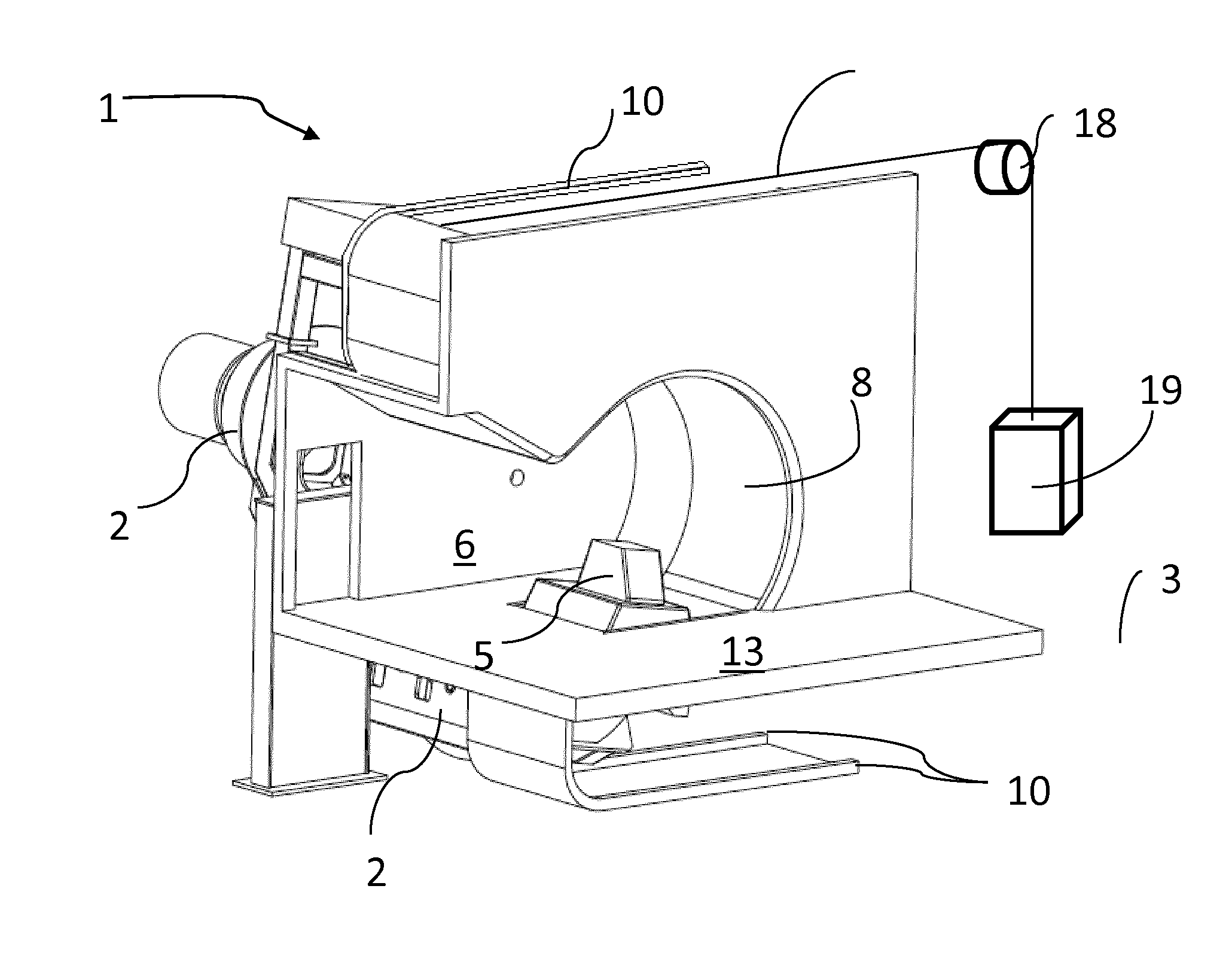
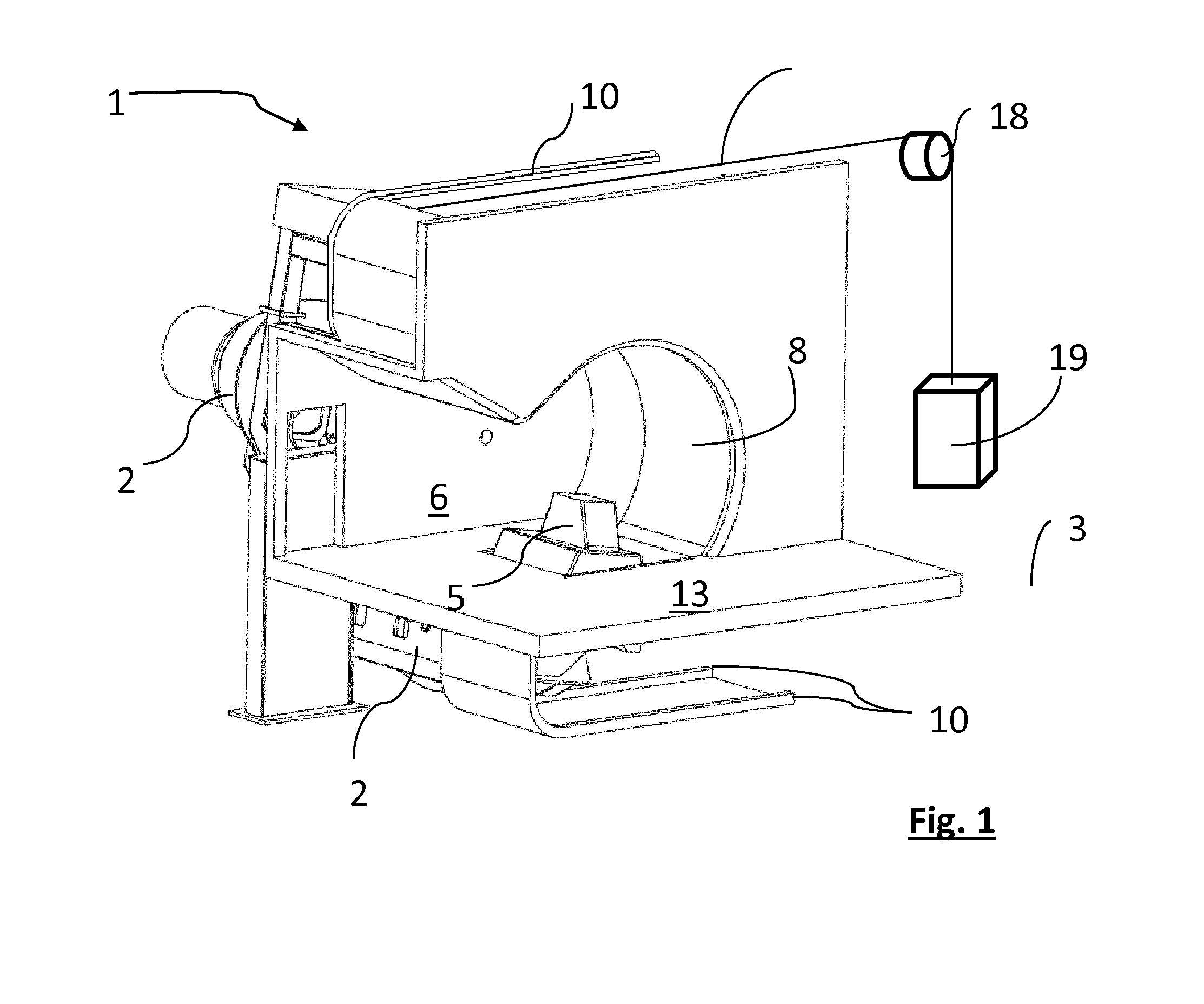
[0048]FIG. 1 shows a hadron therapy installation 1. Such an installation generally comprises an isocentric rotary gantry 2 (not shown). This gantry 2 is capable of rotating about a horizontal axis of rotation 3. The gantry 2 supports a beam transport line (not shown) and an irradiation unit 5 capable of delivering a beam substantially perpendicular to said horizontal axis of rotation 3. The rotary irradiation unit 5 protrudes in a treatment chamber 6 through a passage closed by a moving floor 8.

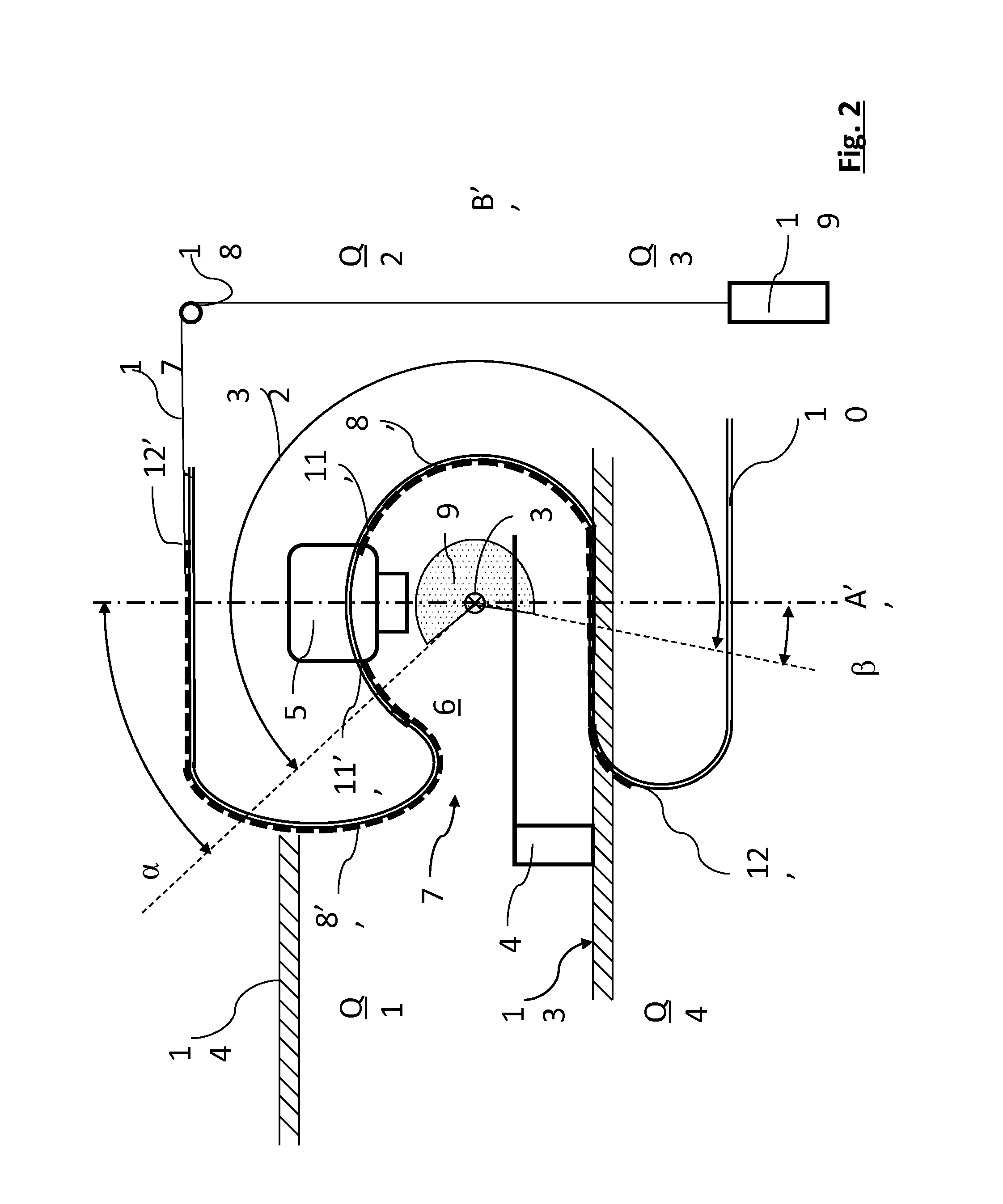
[0049]FIG. 2 shows a simplified cross-section of the hadron therapy installation according to FIG. 1, the cutting plane being perpendicular to the axis of rotation 3 of the irradiation unit 5. The gantry 2 is capable of rotating about the horizontal axis of rotation 3 between a first angular position α and a second angular position β, around the treatment area 9. These angles a and β are measured relative to a vertical plane A′A″ comprising the horizontal axis of rotation 3, α preferably bein...


PUM


Abstract

The invention relates to a hadron therapy installation (1) that comprises a moving floor (8′, 8″) in the form of a deformable band guided in a guide structure (10). A lower segment (8′) can be pulled by the irradiation unit (5) from a lower docked position to a position in which it forms a substantially horizontal floor surface, when the irradiation unit (5) is in a first angular position (a). An upper segment (8″) can be pulled by the irradiation unit (5) from an upper docked position to a position in which it at least partially forms said substantially horizontal floor surface, when the irradiation unit (5) is in a second angular position (β). The lower segment (8′) and the upper segment (8″) are segments with a finite length. A counterweight (19) is connected to the free end of the upper segment (8″), so as to exert a traction force on the latter toward the upper docked position.

Description

TECHNICAL FIELD [0001]The present invention relates to a hadron therapy installation with a moving floor.BACKGROUND OF THE INVENTION[0002]Recent hadron therapy techniques for treating cancers make it possible to deliver a dose precisely on a target volume, for example a tumor, while preserving the surrounding tissue. A hadron therapy installation generally comprises a particle accelerator producing a beam of charged particles, a rotary gantry comprising transport means for the beam, and an irradiation unit. The irradiation unit delivers a dose distribution on the target volume and generally comprises means for monitoring the delivered dose, for example such as an ionization chamber, as well as means for monitoring the direction or shape of the beam.[0003]The rotary gantry is capable of rotating about a horizontal axis of rotation, such that the irradiation unit can deliver a treatment beam at several irradiation angles. The rotary gantries of the traditional hadron therapy installat...

Claims


Application Information

Patent Timeline
IPC IPC(8): A61N5/10
CPCA61N5/1081A61N5/1048A61N2005/1085A61N2005/105A61N2005/1061A61N2005/1087
Inventor PIRET, VINCENT
Owner ION BEAM APPL
Why Eureka
Try Eureka