Hadron therapy installation with moving floor

a technology of moving floor and hadron therapy, which is applied in the field of hadron therapy installation with moving floor, can solve the problems of high risk of moving floor immobilization, large space occupation of hadron therapy installation, and general laborious on-site assembly, and achieve the effect of substantially reducing the risk of the upper segment immobilizing the guide structur

Active Publication Date: 2018-02-27
ION BEAM APPL
View PDF1 Cites 0 Cited by
  • Summary
  • Abstract
  • Description
  • Claims
  • Application Information

AI Technical Summary

Benefits of technology

[0014]According to a first aspect of the invention, a hadron therapy installation that comprises: an irradiation unit with a horizontal axis of rotation capable of rotating around the treatment area between a first angular position (α), situated above the treatment area, and a second angular position (β), situated below the treatment area; a moving floor in the form of a band deformable in the longitudinal direction, comprising a lower segment and an upper segment situated on either side of the irradiation unit; a guide structure guiding the moving floor along a path around the treatment area such that it forms a substantially horizontal floor surface below the treatment area and a wall surrounding the treatment area as far as the first angular position above the floor surface, so as preferably to allow a lateral access bay to exist toward the treatment area. The lower segment can be pulled by the irradiation unit from a lower docked position, in which it is found when the irradiation unit is in the second angular position, to a final operational position, in which it is found when the irradiation unit is in the first angular position, and in which it forms the substantially horizontal floor surface. The upper segment can be pulled by the irradiation unit from an upper docked position, in which it is found when the irradiation unit is in the first angular position, to a final operational position, in which it is found when the irradiation unit is in its second angular position, and in which it at least partially forms the substantially horizontal floor surface. The lower segment and the upper segment are segments with a finite length, each comprising a free end. A traction device is connected to the free end of the upper segment, so as to exert a traction force on the upper segment toward the upper docked position sufficient to keep the upper segment under axial tension independent from the angular position and direction of movement of the irradiation unit. By keeping the upper segment under constant axial tension, over the entire length thereof and independently of the angular position and the direction of movement of the irradiation unit, the risk of that upper segment immobilizing the guide structure is substantially reduced. This is particularly true if the moving floor for example comprises a plurality of transverse segments articulated to each other. It will also be understood that the traction force also at least partially compensates the force exerted by the weight of the lower segment 8′ on the irradiation unit and thereby discharges the latter at least partially. It follows that the motor for rotating the rotary gantry supporting the irradiation unit may be smaller, and that imprecisions in the angular positioning of the irradiation unit, possibly due to a deformation of the rotary gantry under a load, are less significant.

Problems solved by technology

The traditional hadron therapy installations require considerable space, and their on-site assembly is generally fairly labor-intensive.
However, for such a compact moving floor solution, the risk of immobilization of the moving floor is particularly high.

Method used


Image

  • Hadron therapy installation with moving floor
  • Hadron therapy installation with moving floor
  • Hadron therapy installation with moving floor

Examples


Embodiment Construction

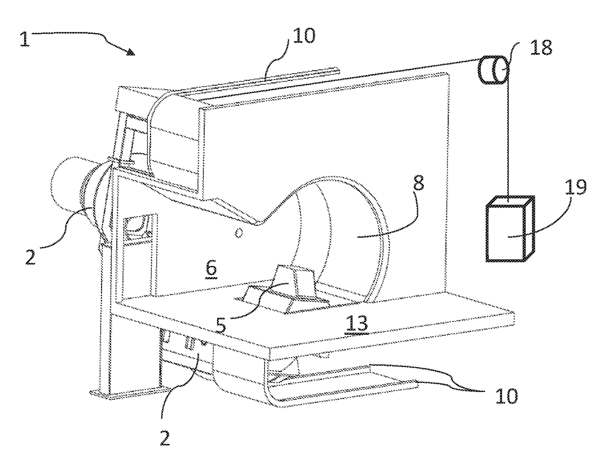
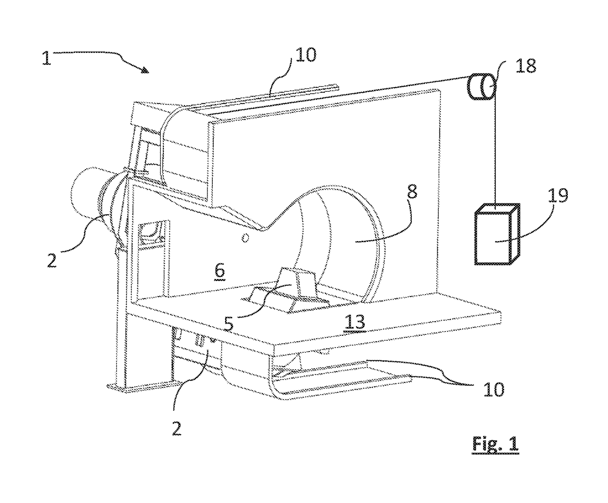
[0048]FIG. 1 shows a hadron therapy installation 1. Such an installation generally comprises an isocentric rotary gantry 2 (not shown). This gantry 2 is capable of rotating about a horizontal axis of rotation 3. The gantry 2 supports a beam transport line (not shown) and an irradiation unit 5 capable of delivering a beam substantially perpendicular to said horizontal axis of rotation 3. The rotary irradiation unit 5 protrudes in a treatment chamber 6 through a passage closed by a moving floor 8.

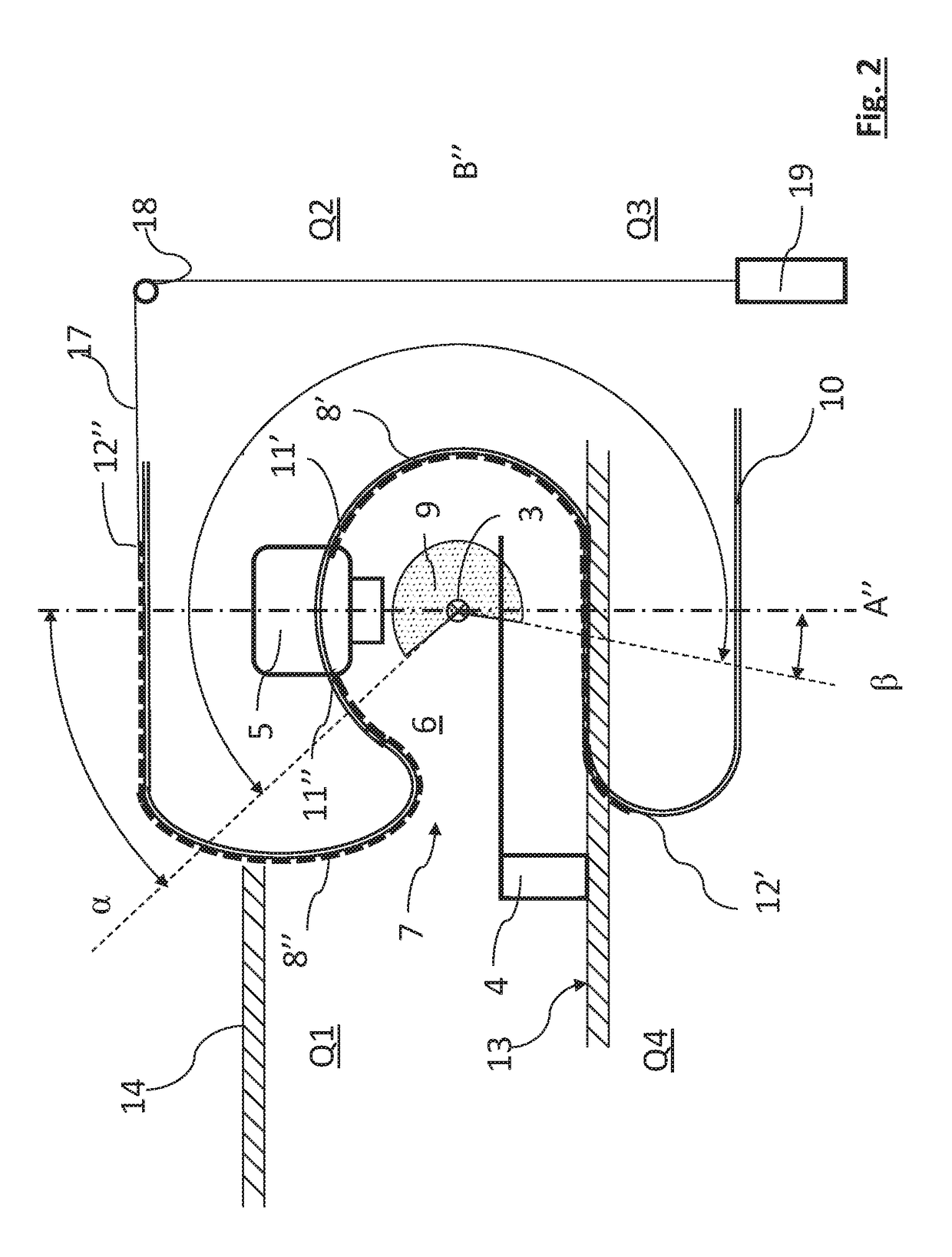
[0049]FIG. 2 shows a simplified cross-section of the hadron therapy installation according to FIG. 1, the cutting plane being perpendicular to the axis of rotation 3 of the irradiation unit 5. The gantry 2 is capable of rotating about the horizontal axis of rotation 3 between a first angular position α and a second angular position β, around the treatment area 9. These angles α and β are measured relative to a vertical plane A′A″ comprising the horizontal axis of rotation 3, α preferably bein...


PUM


Abstract

The present disclosure relates to a hadron therapy installation comprising a moving floor in the form of a deformable band guided in a guide structure. The moving floor comprises a lower segment and an upper segment. The lower segment can be pulled by the irradiation unit from a lower docked position to a position in which the lower segment forms a substantially horizontal floor surface when the irradiation unit is in a first angular position. The upper segment can be pulled by the irradiation unit from an upper docked position to a position in which the upper segment at least partially forms the substantially horizontal floor surface when the irradiation unit is in a second angular position. The lower segment and the upper segment may have a finite length and a counterweight further connected to the free end of the upper segment.

Description

TECHNICAL FIELD[0001]The present invention relates to a hadron therapy installation with a moving floor.BACKGROUND OF THE INVENTION[0002]Recent hadron therapy techniques for treating cancers make it possible to deliver a dose precisely on a target volume, for example a tumor, while preserving the surrounding tissue. A hadron therapy installation generally comprises a particle accelerator producing a beam of charged particles, a rotary gantry comprising transport means for the beam, and an irradiation unit. The irradiation unit delivers a dose distribution on the target volume and generally comprises means for monitoring the delivered dose, for example such as an ionization chamber, as well as means for monitoring the direction or shape of the beam.[0003]The rotary gantry is capable of rotating about a horizontal axis of rotation, such that the irradiation unit can deliver a treatment beam at several irradiation angles. The rotary gantries of the traditional hadron therapy installati...

Claims


Application Information

Patent Timeline
Patent Type & Authority Patents(United States)
IPC IPC(8): A61N5/10
CPCA61N5/1081A61N5/1048A61N2005/1085A61N2005/105A61N2005/1061A61N2005/1087
Inventor PIRET, VINCENT
Owner ION BEAM APPL
Why Eureka
Try Eureka