Thermal protection circuit and electronic device

a protection circuit and electronic device technology, applied in the direction of electrical apparatus construction details, electrical apparatus casings/cabinets/drawers, instruments, etc., can solve the problems of irreversible damage to the electronic device, inability to dissipate generated heat in real-time, and large heat generation of integrated circuits and chips

Inactive Publication Date: 2013-04-11
HONG FU JIN PRECISION IND (SHENZHEN) CO LTD +1
View PDF1 Cites 12 Cited by
  • Summary
  • Abstract
  • Description
  • Claims
  • Application Information

AI Technical Summary

Problems solved by technology

When the electronic device has been operating for an exceedingly long time, the integrated circuits and chips generate a great deal of heat.
Much of the generated heat cannot be dissipated in real-time and may cause irreversible damage to the electronic device.

Method used


Image

  • Thermal protection circuit and electronic device
  • Thermal protection circuit and electronic device
  • Thermal protection circuit and electronic device

Examples


Embodiment Construction

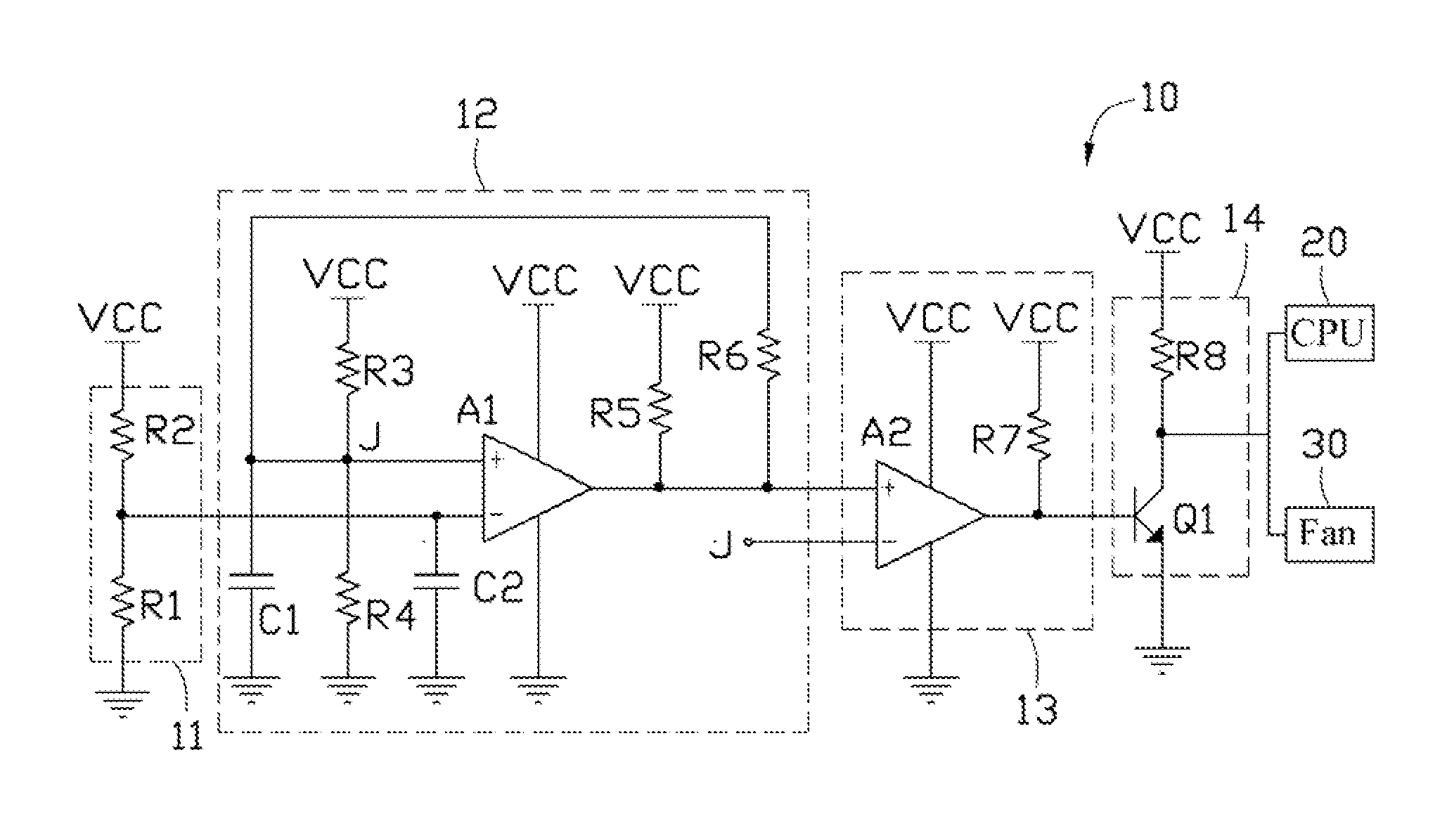
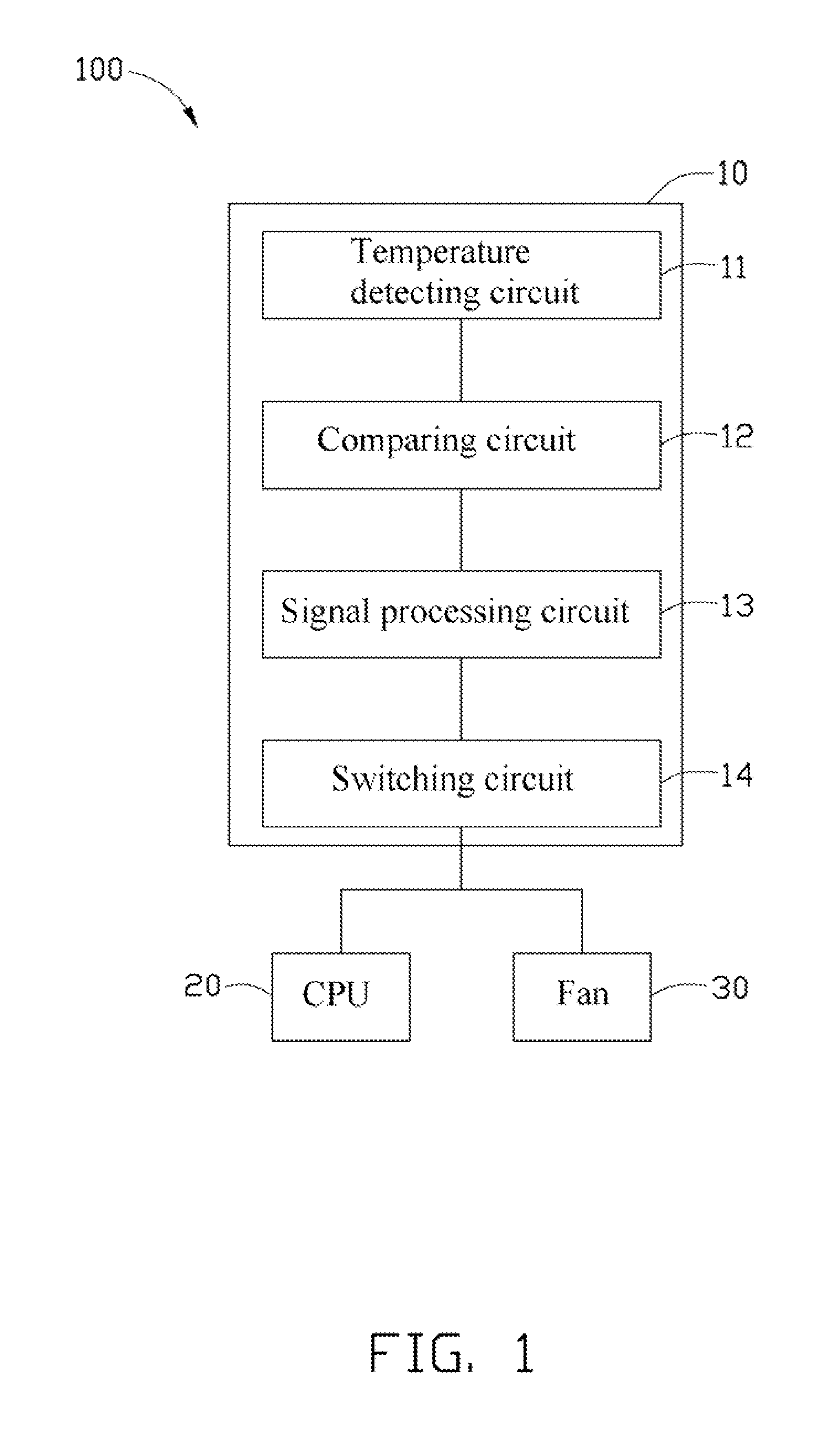
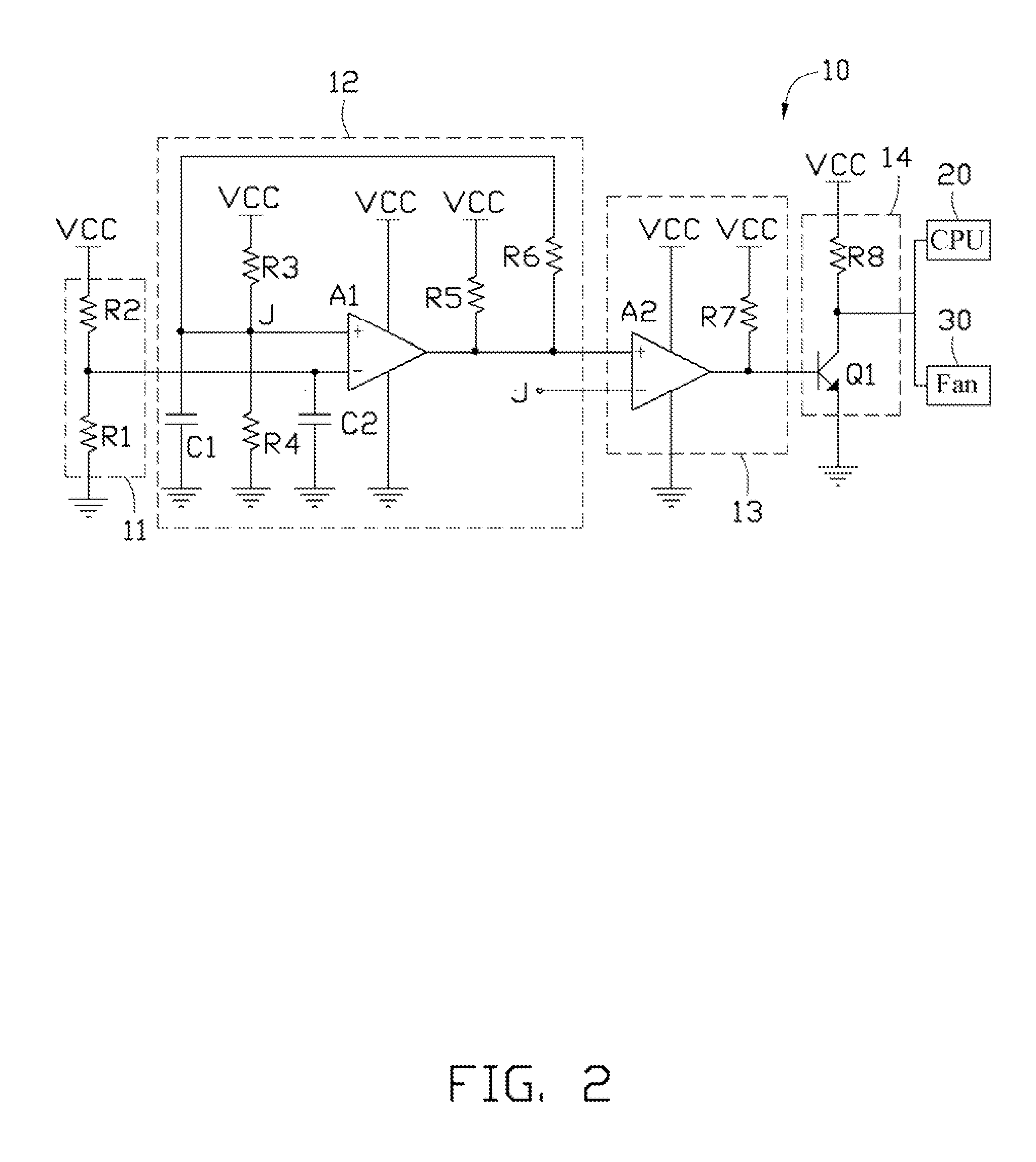
[0010]FIG. 1 is a block diagram of an electronic device, according to an exemplary embodiment. The electronic device 100 includes a thermal protection circuit 10, a central processing unit (CPU) 20, and a fan 30. The protection circuit 10 is connected to both the CPU 20 and the fan 30, and prevents the electronic device 100 from over-heating. In detail, when an internal temperature of the electronic device 100 exceeds a predetermined upper temperature, such as 60° C., the thermal protection circuit 10 drives the CPU 20 to slow a operating frequency of the CPU 20, and increases a rotational speed of the fan 30, thereby lowering internal temperature of the electronic device 100. Once the electronic device 100 cools down to a predetermined lower temperature, such as 25° C., the thermal protection circuit 10 drives the CPU 20 and the fan 30 to work normally, i.e., the CPU 20 recovers to a normally operating frequency, and the fan 30 recovers to a normally rotational speed.

[0011]Also ref...


PUM


Abstract

A thermal protection circuit includes a temperature detecting circuit, a comparing circuit, and a switching circuit. The temperature detecting circuit senses an internal temperature of the electronic device and outputs a voltage signal decreasing proportionally with the internal temperature of the electronic device increasing. The comparing circuit compares the voltage signal to a high voltage threshold or a low voltage threshold, thereby outputting a corresponding driving signal. The switching circuit turns on/off under the control of the driving signal.

Description

BACKGROUND[0001]1. Technical Field[0002]The disclosure generally relates to electronic devices, and particularly to a thermal protection circuit and an electronic device using the thermal protection circuit.[0003]2. Description of the Related Art[0004]A plurality of integrated circuits and chips are employed in an electronic device to satisfy multiple requirements. When the electronic device has been operating for an exceedingly long time, the integrated circuits and chips generate a great deal of heat. Much of the generated heat cannot be dissipated in real-time and may cause irreversible damage to the electronic device.[0005]Therefore, there is room for improvement within the art.BRIEF DESCRIPTION OF THE DRAWINGS[0006]Many aspects of the present embodiment can be better understood with reference to the following drawings. The components in the drawings are not necessarily drawn to scale, the emphasis instead being placed upon clearly illustrating the principles of the present embo...

Claims


Application Information

Patent Timeline
Patent Type & Authority Applications(United States)
IPC IPC(8): H05K7/20H02H5/04
CPCH02H5/042
Inventor LI, JI-CHAODENG, BO
Owner HONG FU JIN PRECISION IND (SHENZHEN) CO LTD
Why Eureka
Try Eureka