Circuit board for an electrical connector

a technology of circuit boards and electrical connectors, applied in the field of circuit boards, can solve problems such as signal degradation

Active Publication Date: 2013-04-11
TYCO ELECTRONICS LOGISTICS AG (CH)
View PDF10 Cites 41 Cited by
  • Summary
  • Abstract
  • Description
  • Claims
  • Application Information

AI Technical Summary

Benefits of technology

[0006]In another embodiment, an electrical connector includes a housing and a contact sub-assembly held by the housing. The contact sub-assembly includes a circuit board and an array of mating contacts that are electrically connected to the circuit board. The mating contacts are arranged in differential pairs. One of the mating contacts of at least one of the differential pairs includes a cross-over section that crosses over the other mating contact of the differential pair. The circuit board includes a substrate having upper and lower sides, and first and second conductive vias extending between the upper and lower sides. The first and second conductive vias include circular outer profiles. The circuit board also includes a differential pair of conductive traces, which includes a first conductive trace having first upper and lower

Problems solved by technology

But, crossing over or bringing the electrical traces closer together may cau

Method used


Image

  • Circuit board for an electrical connector
  • Circuit board for an electrical connector
  • Circuit board for an electrical connector

Examples


Embodiment Construction

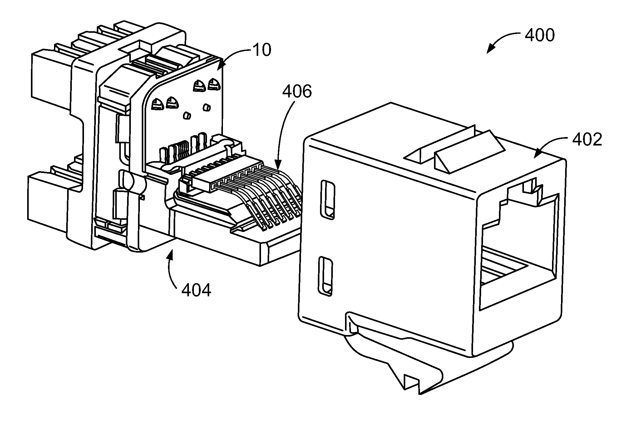
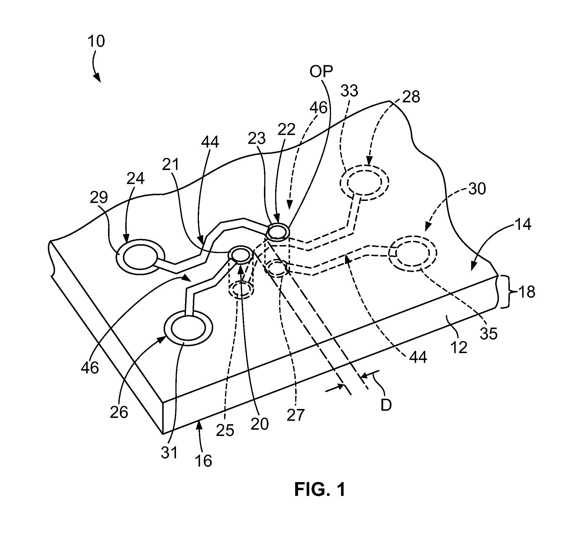
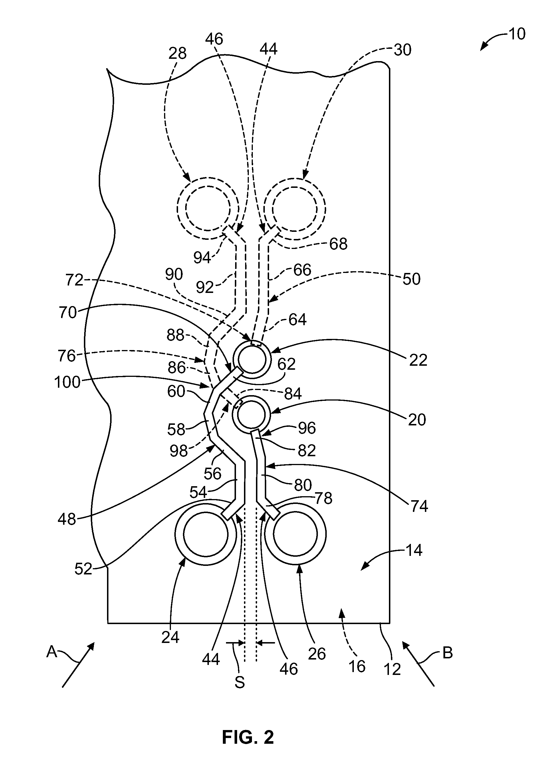
[0015]FIG. 1 is a perspective view of an exemplary embodiment of a circuit board 10. The circuit board 10 includes a substrate 12 having a pair of opposite sides 14 and 16. In the exemplary embodiment, the substrate 12 is defined by a single layer 18. Each of the sides 14 and 16 defines an exterior side of the layer 18. Alternatively, the substrate 12 is defined by plurality of layers (not shown). When the substrate 12 is defined by a plurality of layers, each layer will include at least one side that defines an interior side of the substrate 12. Each of the sides 14 and 16 may be referred to herein as an “upper” side and / or a “lower” side.

[0016]The circuit board 10 includes a plurality of electrically conductive vias 20, 22, 24, 26, 28, and 30. The vias 20 and 22 extend between the sides 14 and 16 of the substrate 12. Specifically, the vias 20 and 22 each extend from the side 14 to the side 16 and completely through the substrate 12 therebetween. The vias 20 and 22 include an elect...


PUM


Abstract

A circuit board includes a substrate having upper and lower sides, and first and second conductive vias extending between the upper and lower sides. The first and second conductive vias include circular outer profiles. The circuit board also includes a differential pair of conductive traces, which includes a first conductive trace having first upper and lower segments disposed on the upper and lower sides, respectively. The first upper and lower segments are electrically connected together through the first conductive via. The first upper segment is curved around the second conductive via such that the first upper segment follows the circular outer profile of the second conductive via. The differential pair of conductive traces also includes a second conductive trace having second upper and lower segments disposed on the upper and lower sides, respectively. The second upper and lower segments are electrically connected together through the second conductive via. The first upper segment crosses over the second lower segment. The second lower segment is curved around the first conductive via such that the second lower segment follows the circular outer profile of the first conductive via.

Description

BACKGROUND OF THE INVENTION[0001]The subject matter described and / or illustrated herein relates generally to circuit boards.[0002]In electrical systems, one source of signal degradation is crosstalk between multiple signal paths. Crosstalk occurs when signals conducted over a signal path are partly transferred by inductive and / or capacitive coupling into another signal path. For example, a typical industry standard type RJ-45 communications connector includes four differential pairs of contacts defining different signal paths. In conventional RJ-45 plug and jack connectors, the differential pairs of contacts extend closely parallel to one another, which may induce crosstalk between and / or among different differential pairs of the contacts.[0003]Various approaches have been implemented to reduce, counteract, and / or suppress crosstalk within RJ-45 connectors. For example, some of the differential pairs of contacts with RJ-45 jack connectors include crossover segments wherein the conta...

Claims


Application Information

Patent Timeline
IPC IPC(8): H01R12/70H05K1/11
CPCH05K1/0228H05K1/0245H05K2201/09245H01R13/6469H01R24/64H05K1/115
Inventor CHAMPION, BRUCE ALLEN
Owner TYCO ELECTRONICS LOGISTICS AG (CH)
Why Eureka
Try Eureka