
Low profile periarticular tension band plating system with soft tissue neutralization cable tunnel/channel

a technology of soft tissue neutralization and tension band, which is applied in the field of fracture plating system, can solve the problems of small bone periarticular fracture, difficult wire placement, and difficult to pla

Active Publication Date: 2013-04-11
NORRIS SURGICAL LLC
View PDF2 Cites 24 Cited by
  • Summary
  • Abstract
  • Description
  • Claims
  • Application Information

AI Technical Summary

Benefits of technology

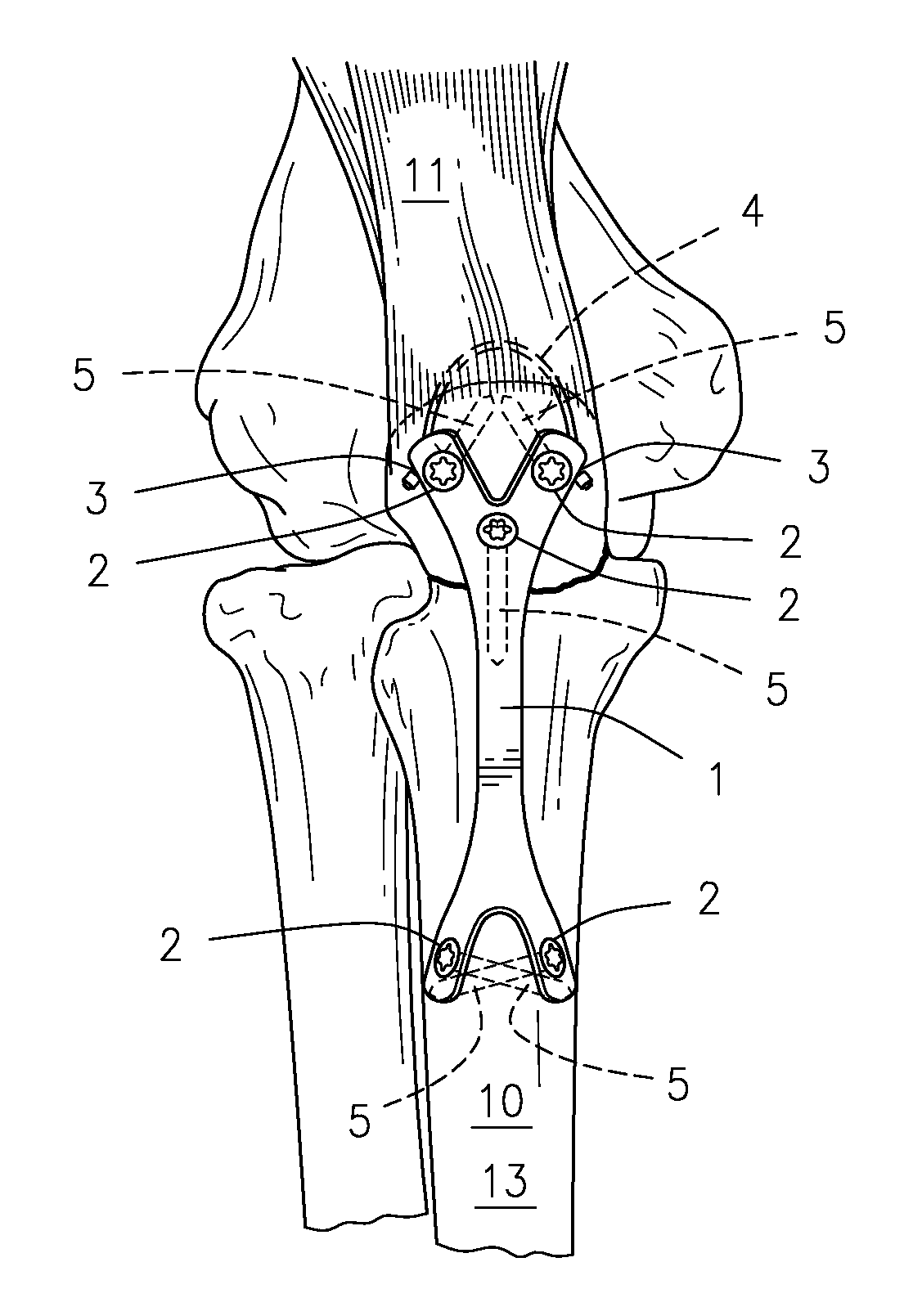
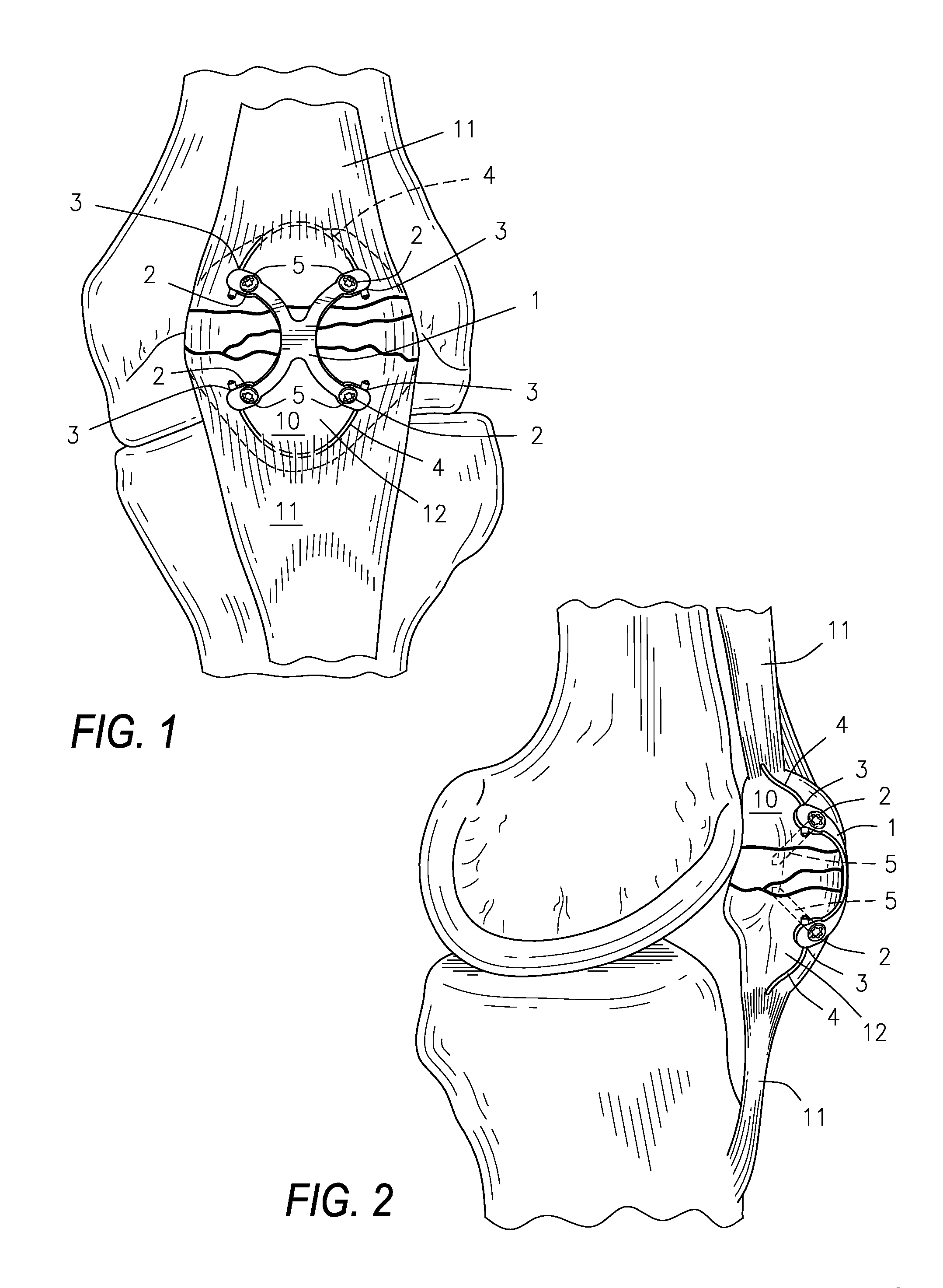
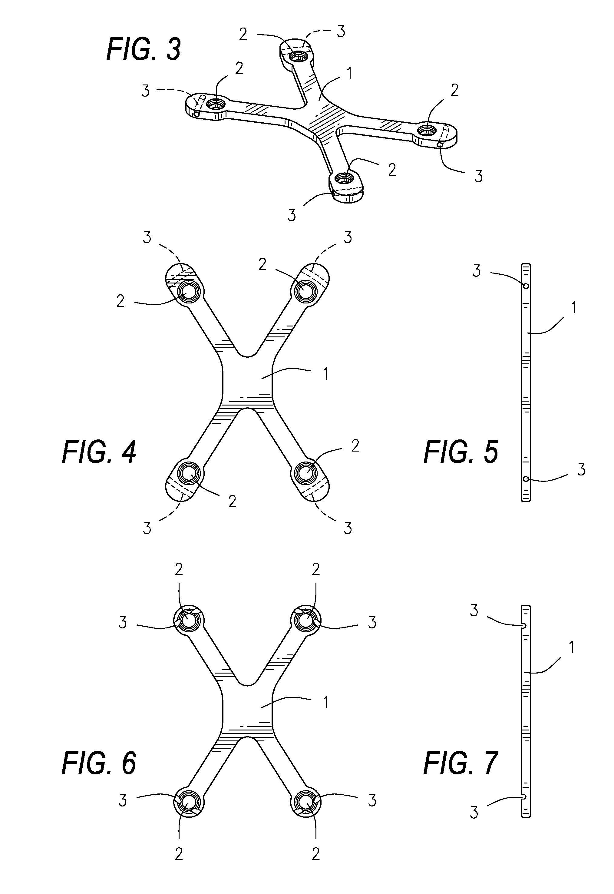
The invention is a bone plating system that includes a plate, a channel or tunnel through the plate, and a flexible device that passes through the channel or tunnel and through soft tissue surrounding the bone. The system can be used to clamp a broken bone, apply the plate to the bone, and unclamp the bone. The system helps to neutralize tensile forces and can be used in various bones such as the patella, olecranon, greater tuberosity, and radial styloid. The plate can be contoured to the bone and attached to the bone with screws. The flexible device can be a cable, suture, wire, or elastic device. The technical effects of the invention include reducing the size of the plate and allowing for easy contouring to the bone, as well as providing a system that helps to neutralize tensile forces and can be used in various bones.

Problems solved by technology

Small bone periarticular fractures, such as fractures around the knee and elbow, can be problematic because of limited soft tissue coverage and the small size of bone fragments.
Fracture plates currently available to treat these simple tensile fractures are bulky and are often prominent, leading to a secondary surgery for hardware removal.
Such wire is difficult to place, remains prominent, and applies a variable and unknown amount of tension.
Another example of traditional cable fixation encircles the bone and induces a variable but often large amount of soft tissue trauma, potentially devitalizing the surrounding bone.

Method used


Image

  • Low profile periarticular tension band plating system with soft tissue neutralization cable tunnel/channel
  • Low profile periarticular tension band plating system with soft tissue neutralization cable tunnel/channel
  • Low profile periarticular tension band plating system with soft tissue neutralization cable tunnel/channel

Examples


Embodiment Construction

[0041]The devices and methods discussed herein are merely illustrative of specific manners in which to make and use this invention and are not to be interpreted as limiting in scope.

[0042]While the devices and methods have been described with a certain degree of particularity, it is to be noted that many modifications may be made in the details of the construction and the arrangement of the devices and components without departing from the spirit and scope of this disclosure. It is understood that the devices and methods are not limited to the embodiments set forth herein for purposes of exemplification.

[0043]In general, in a first aspect, the invention relates to a semi-rigid bone plate that functions as a tension band, combined with soft tissue cabling, suturing, or other flexible device to augment and extend fixation. The device is best used for the surgical repair of simple tensile fractures that occur with relative frequency in specific anatomical regions of the body with minim...


PUM


Abstract

A bone plating system comprising: a plate, where the plate is low-profile and capable of contouring to a bone; a variable number of screw holes, locking or non-locking; at least one channel or tunnel through the plate; and at least one flexible device passing through the channel or tunnel and passing through soft tissue attached to the bone. The low profile plate, in combination with the flexible device passing through the surrounding soft tissue, functions as a tension band and acts to neutralize the muscle forces tending to pull the bone apart at a fracture. The low profile tension band plating system is targeted for periarticular tensile fractures for repair of patella, olecranon, greater trochanter, greater tuberosity, radial styloid, lateral or medial malleoli, or lateral malleolus.

Description

CROSS REFERENCE[0001]Not Applicable.BACKGROUND OF THE INVENTION[0002]1. Field of the Invention[0003]This invention relates generally to a fracture plating system, and more particularly, but not by way of limitation, to a low profile periarticular tension band plating system with soft tissue neutralization cable tunnel / channel.[0004]2. Description of the Related Art[0005]Small bone periarticular fractures, such as fractures around the knee and elbow, can be problematic because of limited soft tissue coverage and the small size of bone fragments. Fracture plates currently available to treat these simple tensile fractures are bulky and are often prominent, leading to a secondary surgery for hardware removal. Current plate systems require suitable bone quantity and quality and a fracture pattern compatible with the device.[0006]Additionally, a figure eight tension band wire is often used for treatment of simple fractures around knee and elbow. Such wire is difficult to place, remains pr...

Claims


Application Information

Patent Timeline
IPC IPC(8): A61B17/88A61B17/80
CPCA61F2/30739A61B17/8085A61B17/842A61B17/8061
Inventor NORRIS, BRENT LANESTAFFORD, PAUL RYANFUNK, DANA JAMES
Owner NORRIS SURGICAL LLC
Learn More