Distributed renewable energy metering

Active Publication Date: 2013-04-11
LENNOX IND
View PDF5 Cites 41 Cited by
  • Summary
  • Abstract
  • Description
  • Claims
  • Application Information

AI Technical Summary

Problems solved by technology

Additionally, the commercial renewable energy installation may be somewhat distributed re

Method used


Image

  • Distributed renewable energy metering
  • Distributed renewable energy metering
  • Distributed renewable energy metering

Examples


Embodiment Construction

[0019]Embodiments of the present disclosure provide a revenue grade renewable energy metering capability for a population or collection of distributed power inverters that generate renewable energy output power and provide corresponding output energy data thereby qualifying for electric utility Performance Based Incentives (PBIs). This revenue grade metering eliminates a need for a separate, dedicated, high-accuracy REC kilowatt-hour meter and may be reported in several formats to onsite and offsite locations.

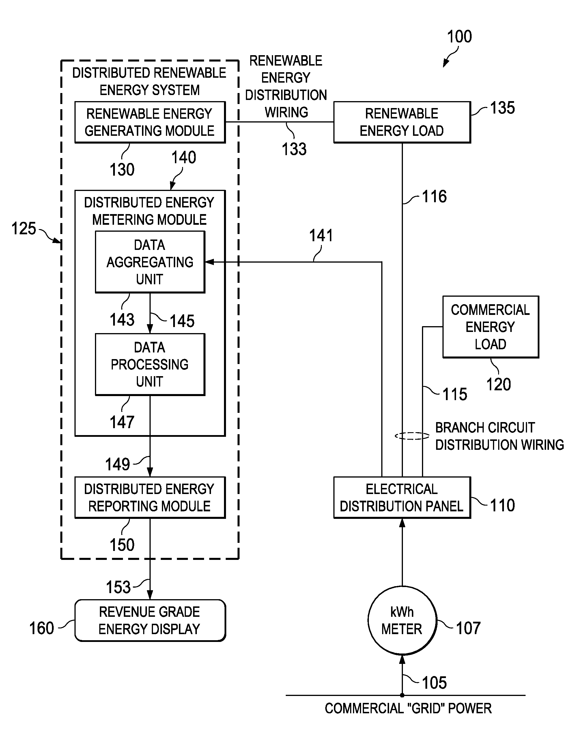
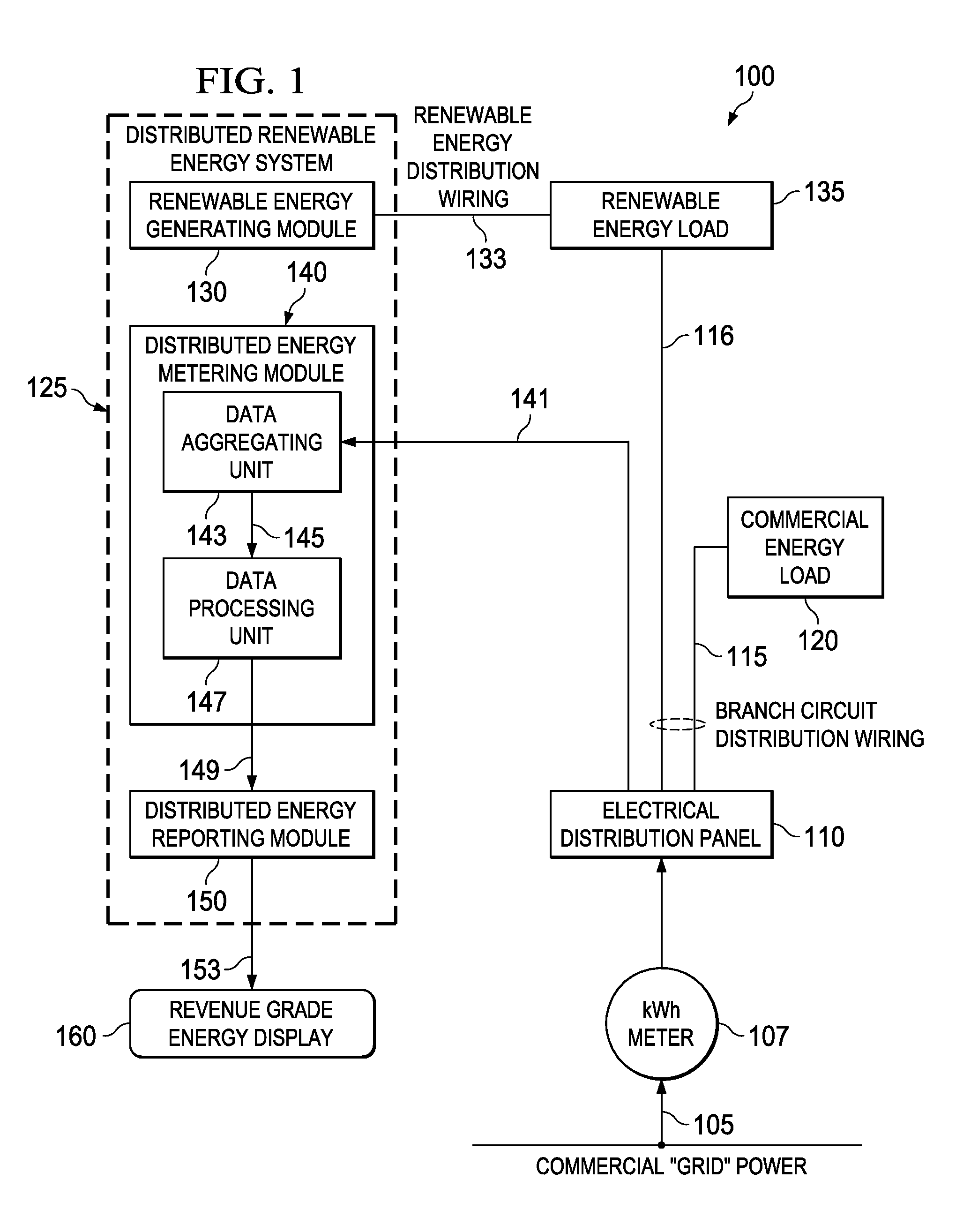
[0020]FIG. 1 illustrates a block diagram of an embodiment of a hybrid energy generation and distribution system, generally designated 100, constructed according to the principles of the present disclosure. The hybrid energy generation and distribution system 100 is representative of an industrial, commercial or residential installation and includes a commercial “grid” electrical service entrance 105, a commercial kilowatt-hour (kWh) meter 107, an electrical distribution panel 1...


PUM


Abstract

A distributed renewable energy system includes a renewable energy generating module having an array of renewable energy generators connected to a population of distributed power inverters. The distributed renewable energy system also includes a distributed energy metering module having a data aggregating unit that receives output energy data from the population of distributed power inverters and a data processing unit that calculates a revenue grade output energy from the output energy data based on a tolerance probability characteristic of the output energy data. The distributed renewable energy system additionally includes a distributed energy reporting module that reports the revenue grade output energy. A method of measuring distributed renewable energy is also provided.

Description

TECHNICAL FIELD[0001]This application is directed, in general, to renewable energy measurement and, more specifically, to a distributed energy metering module, a method of measuring distributed renewable energy and a distributed renewable energy system.BACKGROUND[0002]Mainstream media has extensively covered efforts to reduce reliance on fossil and nuclear fuels in favor of so-called renewable energy, chief among these being solar and wind energy. Residential and business electric power customers have taken steps to reduce their dependence on the commercial electric power distribution network (commonly called “the grid”) and the electric power utilities that sell electric power through it by installing renewable energy systems.[0003]Conventional renewable energy systems typically connect straight back to the electrical distribution panel near the electrical service entrance and kilowatt-hr meter. For these conventional installations, a Renewable Energy Credit (REC) meter (i.e., a re...

Claims


Application Information

Patent Timeline
IPC IPC(8): G06Q99/00
CPCG06Q50/06Y04S10/60G06Q99/00Y04S10/50
Inventor USELTON, ROBERT B.
Owner LENNOX IND
Why Eureka
Try Eureka