

Touch panel
- Summary
- Abstract
- Description
- Claims
- Application Information
AI Technical Summary
Benefits of technology
Problems solved by technology
Method used
Image

Examples
Embodiment Construction
[0018]Certain terms are used throughout the description and following claims to refer to particular components. As one skilled in the art will understand, electronic equipment manufacturers may refer to a component by different names. This document does not intend to distinguish between components that differ in name but not function. In the following description and in the claims, the terms “include” and “comprise” are used in an open-ended fashion, and thus should be interpreted to mean “include, but not limited to . . . ” In addition, to simplify the descriptions and make it more convenient to compare the embodiments between each others, identical components are marked with the same reference numerals in each of the following embodiments. Additionally, the terms like “first” and “second” in this context are only used to distinguish different components and do not constrain the order of generation.
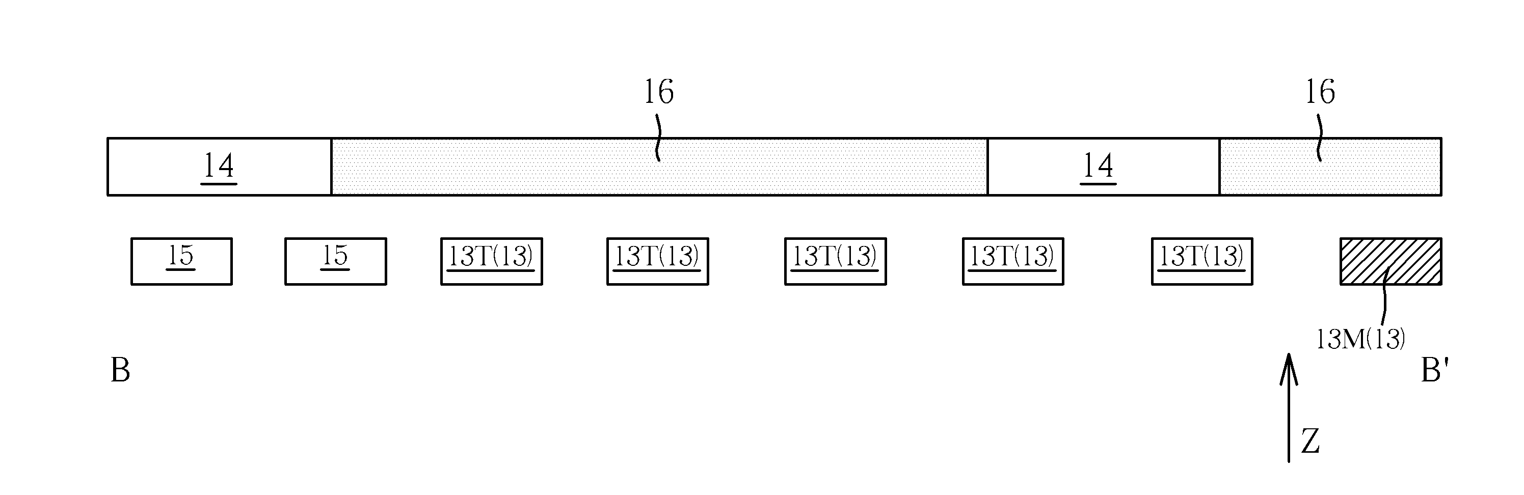
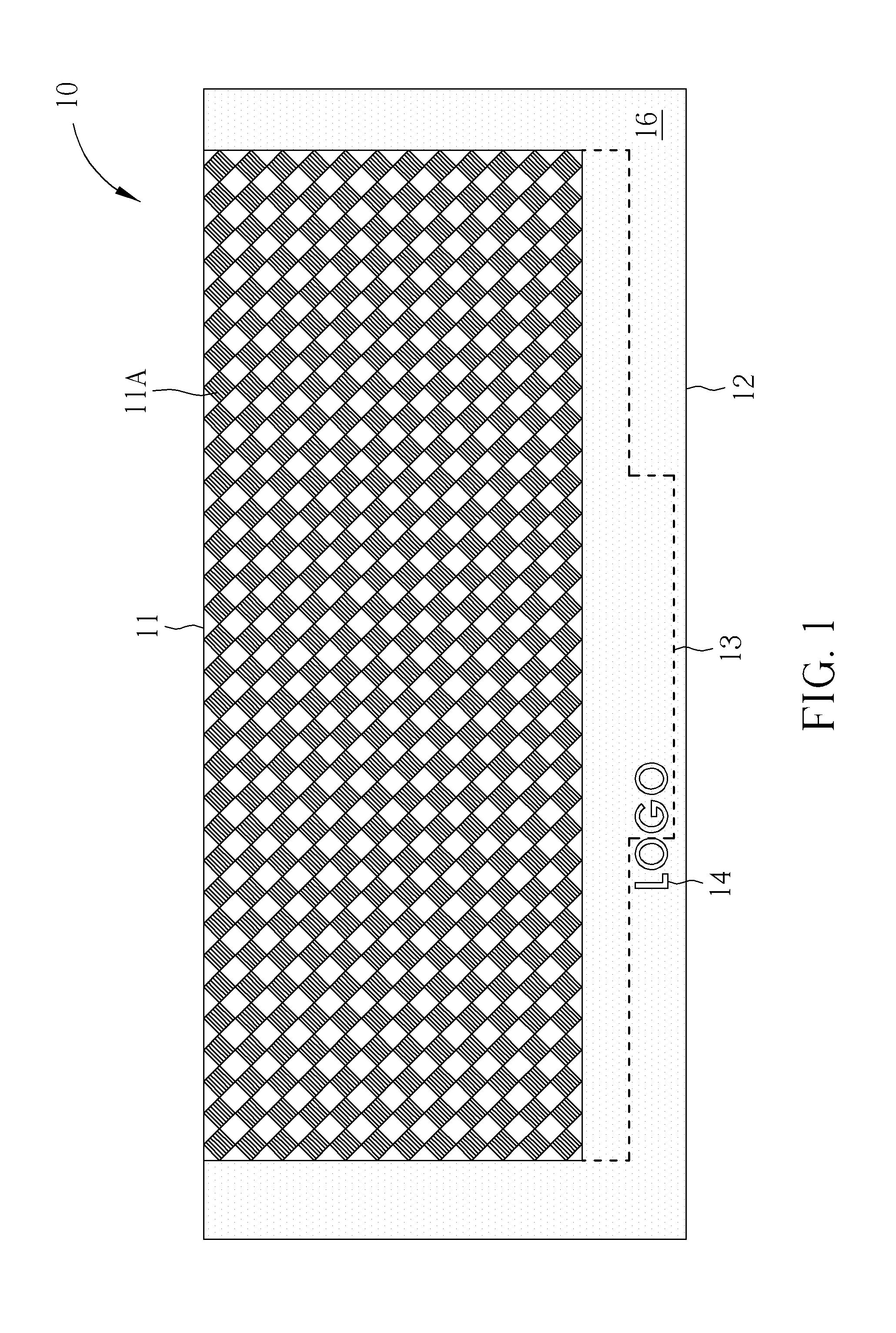
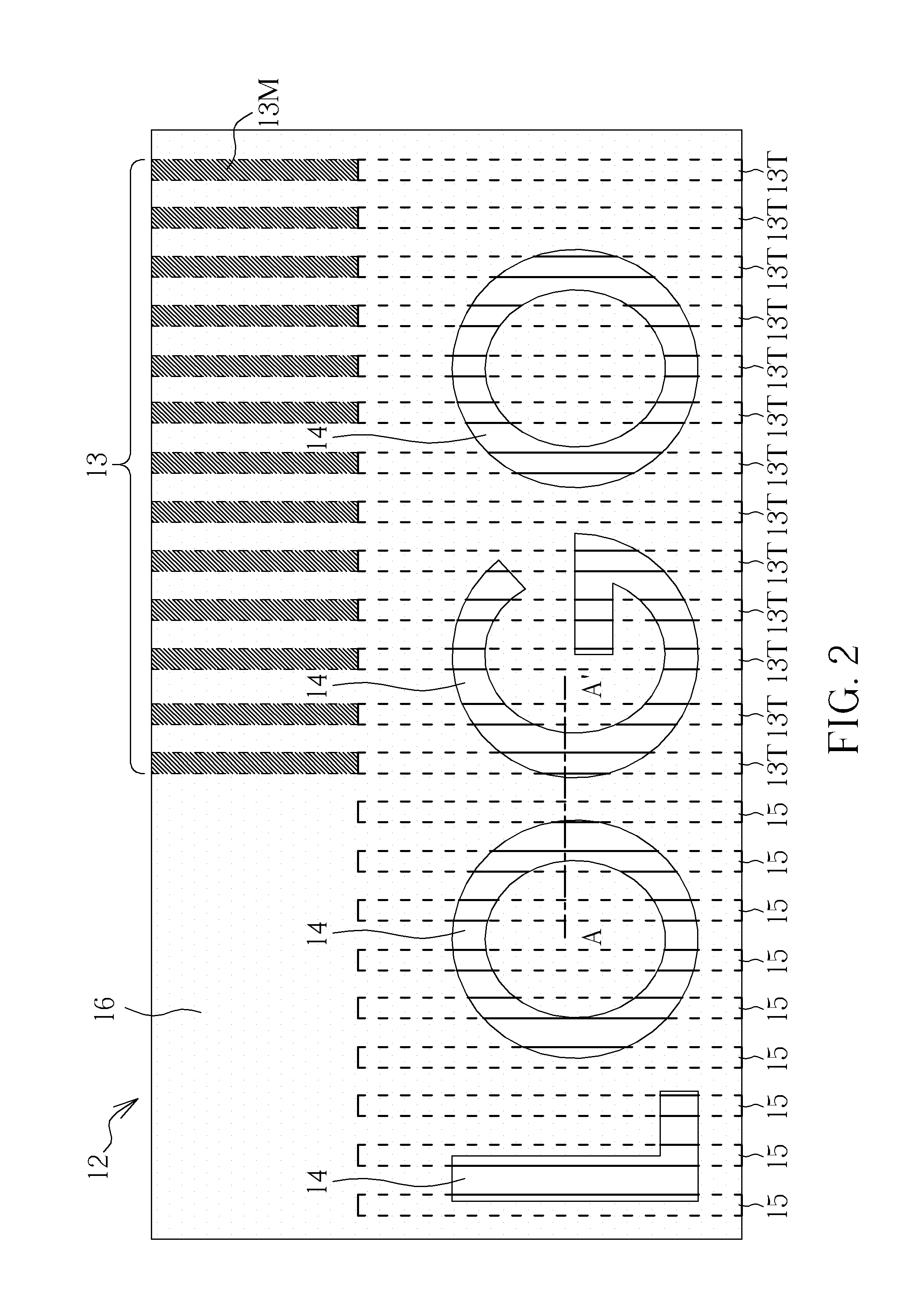
[0019]Please refer to FIGS. 1-3. FIG. 1 is a top view illustrating a touch panel in ...
PUM
 Abstract
Description
Claims
Application Information