Combiner box

Inactive Publication Date: 2013-04-18
YANG CHI JEN
View PDF9 Cites 10 Cited by
  • Summary
  • Abstract
  • Description
  • Claims
  • Application Information

AI Technical Summary

Benefits of technology

The present invention aims to provide a combination box that is easy to install and less expensive to make.

Problems solved by technology

The conventional combiner box 1 includes a relatively large number of the input terminal blocks 14, and therefore, a manufacturing cost of the conventional combiner box 1 is relatively high.
Further, an electrical technician is required for wiring the conventional combiner box 1 and the wiring operation is a relatively complicated process.
As a result, there is a high risk of human error during installation of the conventional combiner box 1, and the installation is time-consuming so that labor-related costs are high.

Method used


Image

  • Combiner box
  • Combiner box
  • Combiner box

Examples


Embodiment Construction

[0026]Before the present invention is described in greater detail, it should be noted that like elements are denoted by the same reference numerals throughout the disclosure.

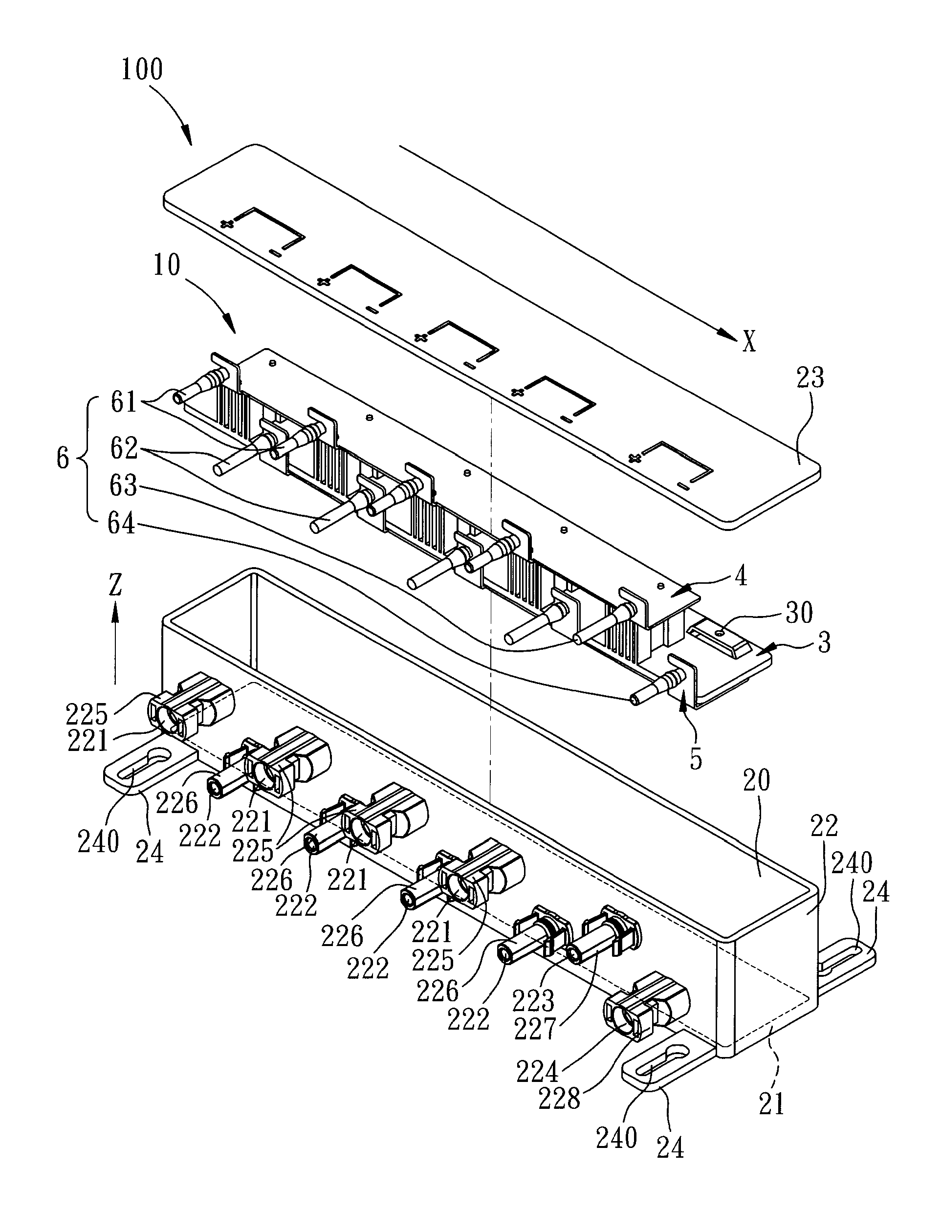
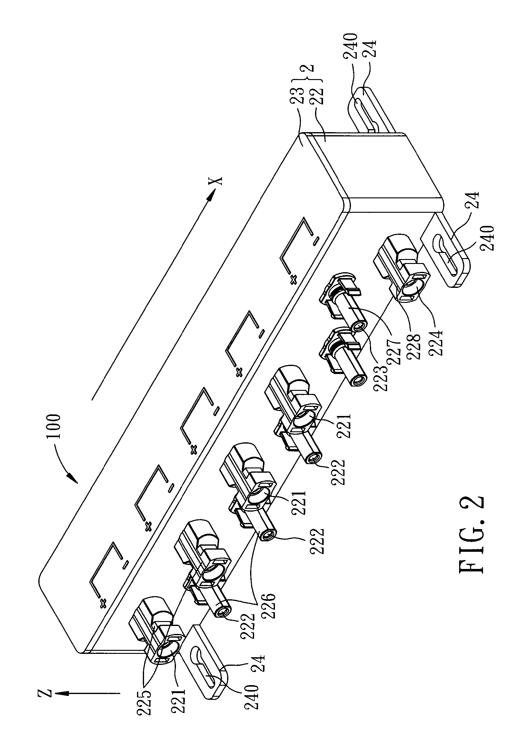
[0027]Referring to FIGS. 2 to 4, a first preferred embodiment of a combiner box 100 of this invention includes a casing 2, a combiner module 10 disposed in the casing 2, and an electrical connector unit 6.

[0028]In this embodiment, the casing 2 is in a rectangular shape, and includes a bottom wall 21, a surrounding wall 22, a cover plate 23, and a plurality of mounting plates 24. The bottom wall 21 and the surrounding wall 22 cooperatively define an accommodating space 20, and the cover 23 removably covers on the surrounding wall 22 to close the accommodating space 20. For the purpose of convenience of illustration, a direction parallel to one side of the surrounding wall 22 (e.g., a lengthwise side) is defined as a first direction (X), and a direction perpendicular to the bottom wall 21 (i.e., a height direction...


PUM


Abstract

A combiner box includes a combiner module and an electrical connector unit disposed in a casing. The combiner module includes an insulating board, and plural first and second input electrodes disposed on opposite surfaces of the insulating board along a first direction and corresponding respectively to plural first and second input sockets of the casing. The second input sockets are disposed below and alternatingly arranged with the first input sockets along the first direction. The electrical connector unit includes plural first and second input terminals disposed in the first and second input sockets and electrically connected to the first and second input electrodes, respectively.

Description

CROSS-REFERENCE TO RELATED APPLICATION[0001]This application claims priority of Taiwanese Application No. 100219485, filed on Oct. 18, 2011.BACKGROUND OF THE INVENTION[0002]1. Field of the Invention[0003]The present invention relates to a combiner box, more particularly to a combiner box for combining multiple current inputs into one current output.[0004]2. Description of the Related Art[0005]In solar energy generation, the combiner box is an electrical distribution box used for combining multiple direct-current (DC) inputs coming from respective solar panels so as to convert the DC inputs into one DC output. For example, FIG. 1 illustrates a conventional combiner box 1 including a waterproof casing 11, a surge protector 12, a plurality of fuses 13, a plurality of input terminal blocks 14, a plurality of input connectors 15, a pair of output connectors 16, a DC breaker 17, and a conducting wire unit 18.[0006]The waterproof casing 11, for example, satisfies an ingress protection rati...

Claims


Application Information

Patent Timeline
IPC IPC(8): H02B1/00
CPCH01L31/0485H02G3/08H02G3/16H02S40/34H01L2924/0002Y02E10/50H01L2924/00
Inventor YANG, CHI-JEN
Owner YANG CHI JEN
Why Eureka
Try Eureka