Rotatable connector device

a technology of rotatable connectors and connectors, which is applied in the maintenance of line connectors, current collectors, electric/fluid circuits, etc., can solve the problems of rotatable connectors, deterioration of the operability of rotatable connectors, and broken cs, so as to reduce the amount of foreign objects entering the accommodation space and prevent the generation of unusual sounds

Active Publication Date: 2013-04-18
FURUKAWA AUTOMOTIVE SYST +1
View PDF17 Cites 10 Cited by
  • Summary
  • Abstract
  • Description
  • Claims
  • Application Information

AI Technical Summary

Benefits of technology

[0028]According to the present invention, the gap formed between the rotator and the stator is opened in a direction crossing the diametric direction. Therefore, the foreign object cannot easily enter the accommodation space of the rotatable connector device from the clearance between the steering lower cover and the column cover, and thus the amount of the foreign object entering the accommodation space can be decreased as compared with in the conventional structure. Owing to this, the breakage of the flat cables, delamination of the lamination covers of the flat cables to cause shortcircuiting, or generation of an unusual sound can be prevented.

Problems solved by technology

However, the rotatable connector has the following problem.
As a result, there occur problems that the flat cables C are broken, lamination covers of the flat cables C are delaminated to cause shortcircuiting, or an unusual sound is generated when the flat cables C are rubbed with each other.
There is another problem that the resistance against pivoting of the stator 12 and the rotator 13 is increased to deteriorate the operability of the rotatable connector.

Method used


Image

  • Rotatable connector device
  • Rotatable connector device
  • Rotatable connector device

Examples


Embodiment Construction

[0036]Hereinafter, an embodiment of the present invention will be described with reference to the drawings.

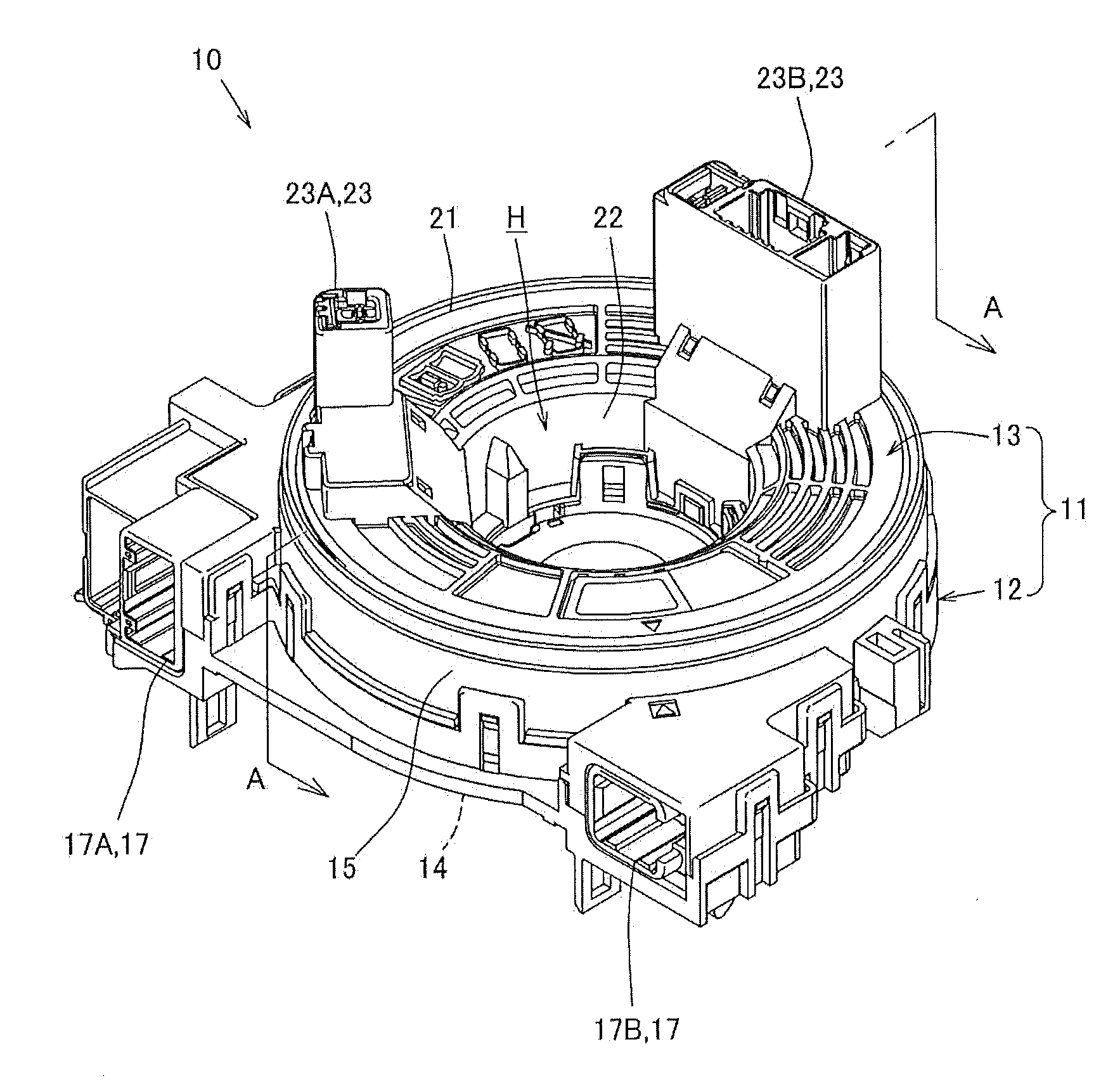
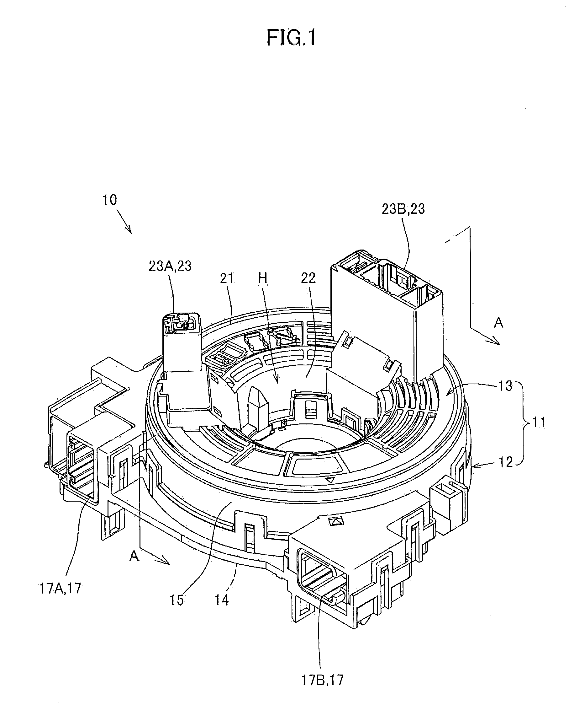
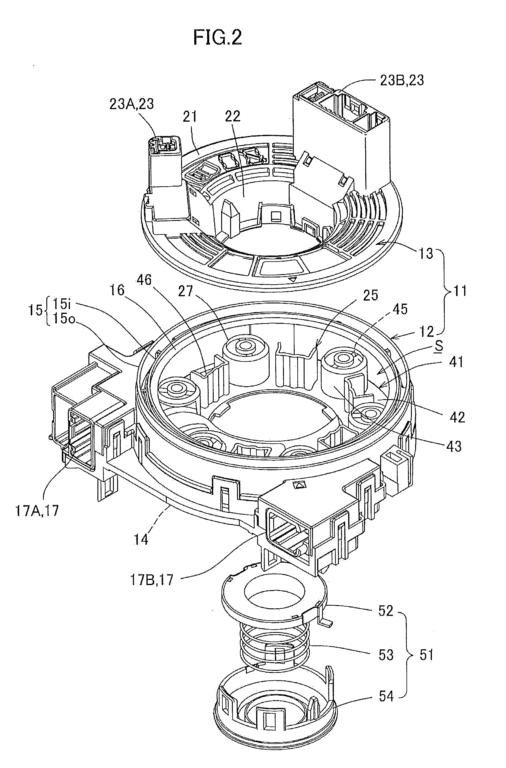
[0037]As shown in FIG. 1 through FIG. 5, a steering roll connector 10 (SRC) in this embodiment includes a cable housing 11, a retainer 41, and a rotation lock unit 51.

[0038]FIG. 1 and FIG. 2 are respectively an external view and an exploded isometric view of the steering roll connector. FIG. 3 is a plan view of the steering roll connector in the state where a rotator described later is detached. FIG. 4 is a cross-sectional view of FIG. 1 taken along line A-A in FIG. 1. FIG. 5 is an enlarged end view showing a part of FIG. 4.

[0039]The cable housing 11 is formed to have a generally cylindrical shape having an insertion hole H at a center thereof when seen in a plan view. The insertion hole H runs through the cable housing 11 in an axial direction of a steering shaft (not shown). The insertion hole H is formed to have a diameter which allows the steering shaft supported by the ste...


PUM


Abstract

A rotatable connector device has a rotator including a ring-shaped rotatable-side ring plate and an inner cylindrical section having a cylindrical shape and formed along an inner circumferential edge of the rotatable-side ring plate, and a stator including a ring-shaped fixed-side ring plate and an outer cylindrical section having a cylindrical shape and formed along an outer circumferential edge of the ring-shaped fixed-side ring plate. The rotator and the stator are engaged with each other, so as to be pivotable with respect to each other with a gap being provided between the rotatable-side ring plate and the outer cylindrical section. An accommodation section, defined by the rotatable-side ring plate and the inner cylindrical section of the rotator and the fixed-side ring plate and the outer cylindrical section of the stator, accommodates a cable for electrically connecting the rotator and the stator to each.

Description

TECHNICAL FIELD[0001]The present invention relates to a rotatable connector device mountable on a vehicle such as an automobile or the like, and specifically to a connector device usable for electrically connecting elements on the side of a steering wheel and a vehicle body side to each other.BACKGROUND ART[0002]A rotatable connector device such as a steering roll connector or the like which is mountable on a vehicle such as an automobile or the like includes a cable housing having a stator (fixed case) and a rotator (rotatable case) which are coaxially attached to each other so as to be rotatable with respect to each other.[0003]In the cable housing of such a rotatable connector device, the stator is fixed to a vehicle body and the rotator is attached to the steering wheel. In addition, the rotatable connector device electrically connects the vehicle body side and elements on the side of the steering wheel, for example, a horn module, an airbag module and the like via flat cables a...

Claims


Application Information

Patent Timeline
Patent Type & Authority Applications(United States)
IPC IPC(8): H01R39/00
CPCH01R39/00B60R16/027H01R43/002H01R35/025
Inventor HIRAI, SHUJI
Owner FURUKAWA AUTOMOTIVE SYST
Why Eureka
Try Eureka