
Heating device for the ironing top of an ironing board

a heating device and ironing board technology, which is applied in the direction of ironing pads, washing machines, textiles and paper, etc., can solve the problems of inconvenient transportation, inconvenient heating, and inability to heat and dampen garments being ironed in a way that is entirely undesired, and achieves the effect of reducing the cost of production, and increasing the complexity of the heating system

Inactive Publication Date: 2013-04-25
GIMI
View PDF3 Cites 4 Cited by
  • Summary
  • Abstract
  • Description
  • Claims
  • Application Information

AI Technical Summary

Benefits of technology

The present invention aims to provide a heating device for the ironing top of a hot ironing board that overcomes the drawbacks of existing heating devices. The device is lightweight, easy to install and can be used on existing ironing boards. It is designed to be cost-effective and implementable using existing systems and technologies. The device includes a flexible flat element that can be quickly and reversibly fixed to the ironing top of the ironing board.

Problems solved by technology

Indeed, the steam, if emitted in excessive quantities, or if sprayed on a part of a garment being ironed that is far from the heat of the iron, cools and dampens or wets the garment being ironed in a way that is entirely undesired.
The known systems, although effective, make the ironing board, meaning the object in its entirety comprising ironing top and a supporting frame which can generally be folded flat for minimal encumbrance, very heavy and inconvenient to transport.
Moreover, producing such an ironing board with the ironing top heating system integrated is much more complex and and expensive than making a normal ironing board.
Another drawback of the known heating devices is constituted by the fact that the heating layer is generally under the ironing top, i.e. under the plate-like element that forms the rigid support surface against which the iron is pressed to perform the ironing.
In this way the heating layer is actually located relatively far from the garment being ironed, and its efficiency is reduced by the interposition of layers with low thermal conductivity between the heating layer and the garment being ironed.
A further drawback of the known heating devices for an ironing top is constituted by the fact that if, as is generally the case, the ironing top is constituted by a plate-like element made of metal, and its supporting structure is also made of metal, then the ironing top itself and the parts of the frame that support it produce a thermal inertia that retains and diffuses the heat emitted by the heating means, thus wastefully dispersing it and also heating parts of the ironing board which may remain hot for a long time, making the manageability of the ironing board by a user problematic into the bargain.

Method used


Image

  • Heating device for the ironing top of an ironing board
  • Heating device for the ironing top of an ironing board
  • Heating device for the ironing top of an ironing board

Examples


first embodiment

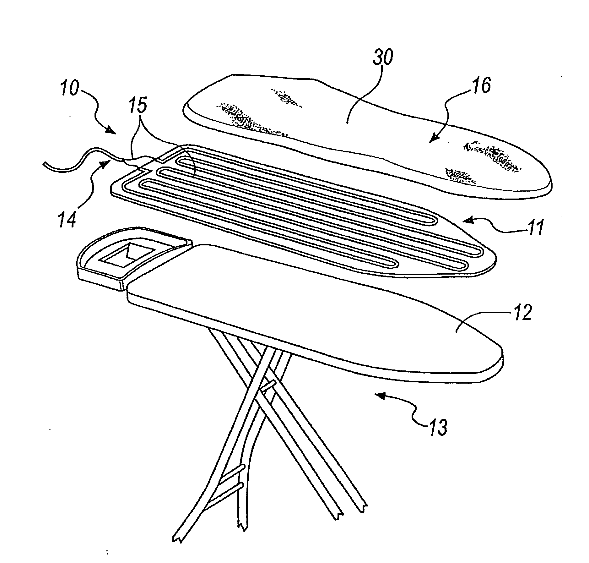
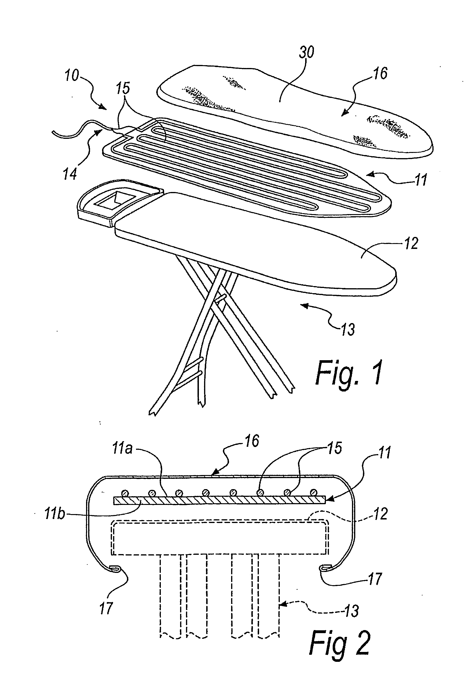
[0029]With reference to the figures, a heating device 10 for the ironing top of an ironing board, according to the invention, is indicated in its first embodiment with the reference numeral 10.

[0030]This heating device 10 comprises a flexible flat element 11, shaped to address an ironing top 12 of a generic ironing board 13.

[0031]In this first embodiment of the invention, the flexible flat element 11 is constituted by a flannel, i.e., by a sheet of plush cloth.

[0032]This flexible flat element 11 is provided with heating means 14, which are positioned so as to affect at least part of at least one of its main surfaces 11a and 11b.

[0033]In this first embodiment of the device 10, the heating means 14 are constituted by an electric heating cable 15, of a type that is known per se, distributed over the top surface, in a configuration of use, 11a.

[0034]The heating cable 15 is arranged for example in a coil as shown in FIG. 1.

[0035]In a different embodiment of the invention, instead of th...

second embodiment

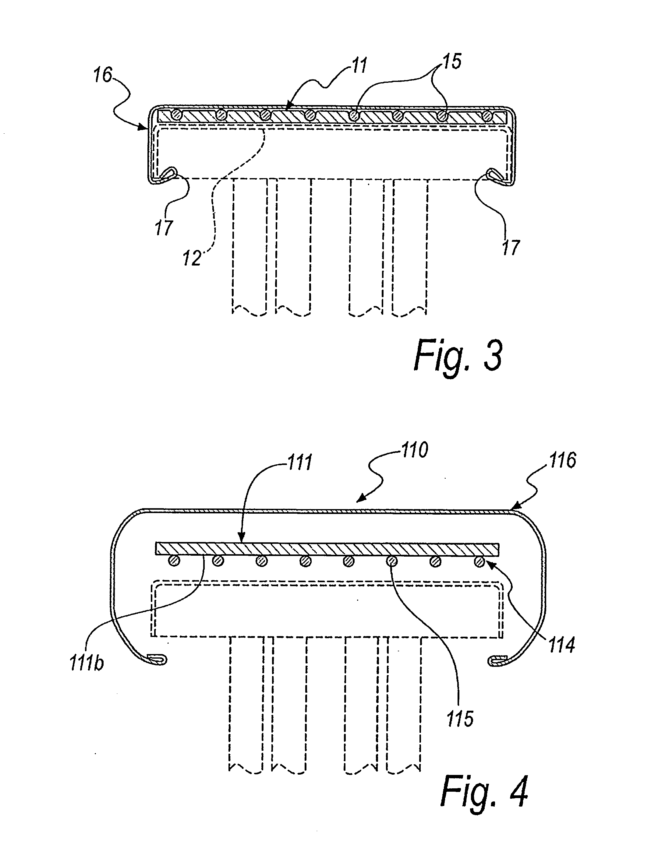
[0040]In the device according to the invention, shown schematically by the cross-section in FIG. 4 and indicated therein with the reference numeral 110, the heating means 114, i.e. for example the heating cable 115, are arranged on the lower surface 111b of the flexible flat element 111.

[0041]In this position the planarity of the ironing surface of the cover 116, in a configuration of use, is improved.

third embodiment

[0042]FIGS. 5 and 6 show the heating device according to the invention, indicated therein with the reference numeral 210.

[0043]In the third embodiment, the flexible flat element 211, which carries the heating means 214 on its lower surface 211b, is associated with a second flexible flat element 220, shaped likewise and adapted to be interposed between the first flat element 211 and the ironing top 212, so as to improve the thermal insulation of the heating means towards the ironing top itself, which is generally made of metal.

[0044]The heating cable 215, or other similar element, is therefore sandwiched between the two flexible flat elements, which, for example, can both be flannels.

[0045]It should be noted that the second flat element 220 can also be made from other, similar and equivalent materials, according to necessity and requirements.

[0046]The sandwich comprising the first flat element 211 and the second flat element 220 is held against the ironing top 212 by the cover 216.


PUM


Abstract

A heating device for the ironing top of an ironing board, comprising a flexible flat element, to be associated with a top of an ironing board, provided with heating elements arranged so as to affect at least part of at least one of its main surfaces. Advantageously, the device comprises elements for the quick and reversible fixing of the flexible flat element to an ironing top.

Description

[0001]The present invention relates to a heating device for the ironing top of an ironing board.BACKGROUND OF THE INVENTION[0002]Nowadays there are many known heating devices for the ironing top of an ironing board.[0003]Heating the ironing top rapidly evaporates the humidity that may penetrate the garment being ironed which is sometimes struck by a jet of steam or lightly sprayed with water by other means external to the iron, such as a spray bottle, an asperser, or other similar means.[0004]Indeed, the steam, if emitted in excessive quantities, or if sprayed on a part of a garment being ironed that is far from the heat of the iron, cools and dampens or wets the garment being ironed in a way that is entirely undesired.[0005]The systems for heating an ironing top are often of the electric type, and sometimes of the fluid type.[0006]The known systems have the common characteristic of being integrated within the structure of the ironing top, or stably fixed to the top or bottom thereo...

Claims


Application Information

Patent Timeline
IPC IPC(8): D06F83/00H05B3/34
CPCD06F81/08H05B2203/003H05B3/26D06F83/00
Inventor HEM, SUDHANA
Owner GIMI
Learn More