Foil cartridge and method for producing a foil cartridge

Inactive Publication Date: 2013-04-25
HILTI AG
View PDF21 Cites 4 Cited by
  • Summary
  • Abstract
  • Description
  • Claims
  • Application Information

AI Technical Summary

Benefits of technology

[0029]It is possible to achieve long storage periods because the chambers are hermetically sealed and separated from one another and the leakage rate is virtually zero due to the design of the chambers.
[0030]Independent of the number of components used, the outer geometry of the foil cartridge may be designed to be the same. This makes it possible to use one dispensing device for different types of filling materials.
[0031]The outlet opening may also remain unsealed. In this case, the discharge opening is preferably sealed by a closure provided with a weakened zone, and when the dispensing pressure is applied when inserting a still sealed new foil cartridge into

Problems solved by technology

However, the disadvantage of this is, for one, that the axial ends of the chamber are not hermetically sealed so that there is always a certain amount of leakage especially of the mobile liquid content to some extent from the capillary forces in the “ponytail.” Secondly, there is the

Method used


Image

  • Foil cartridge and method for producing a foil cartridge
  • Foil cartridge and method for producing a foil cartridge
  • Foil cartridge and method for producing a foil cartridge

Examples


Example

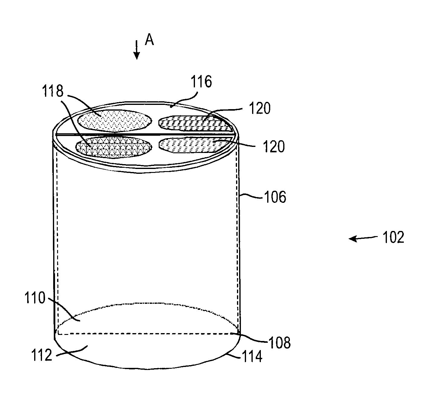
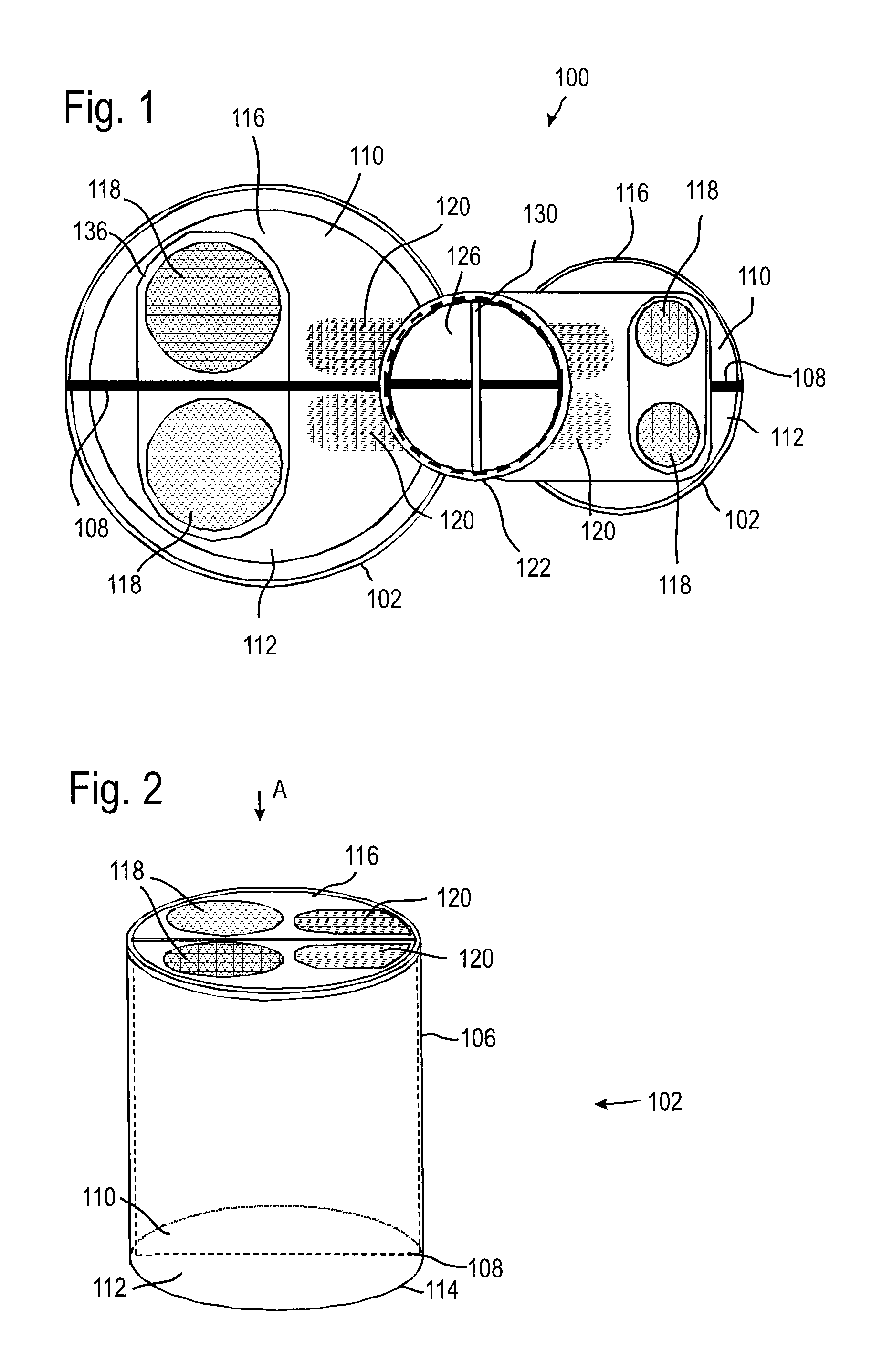
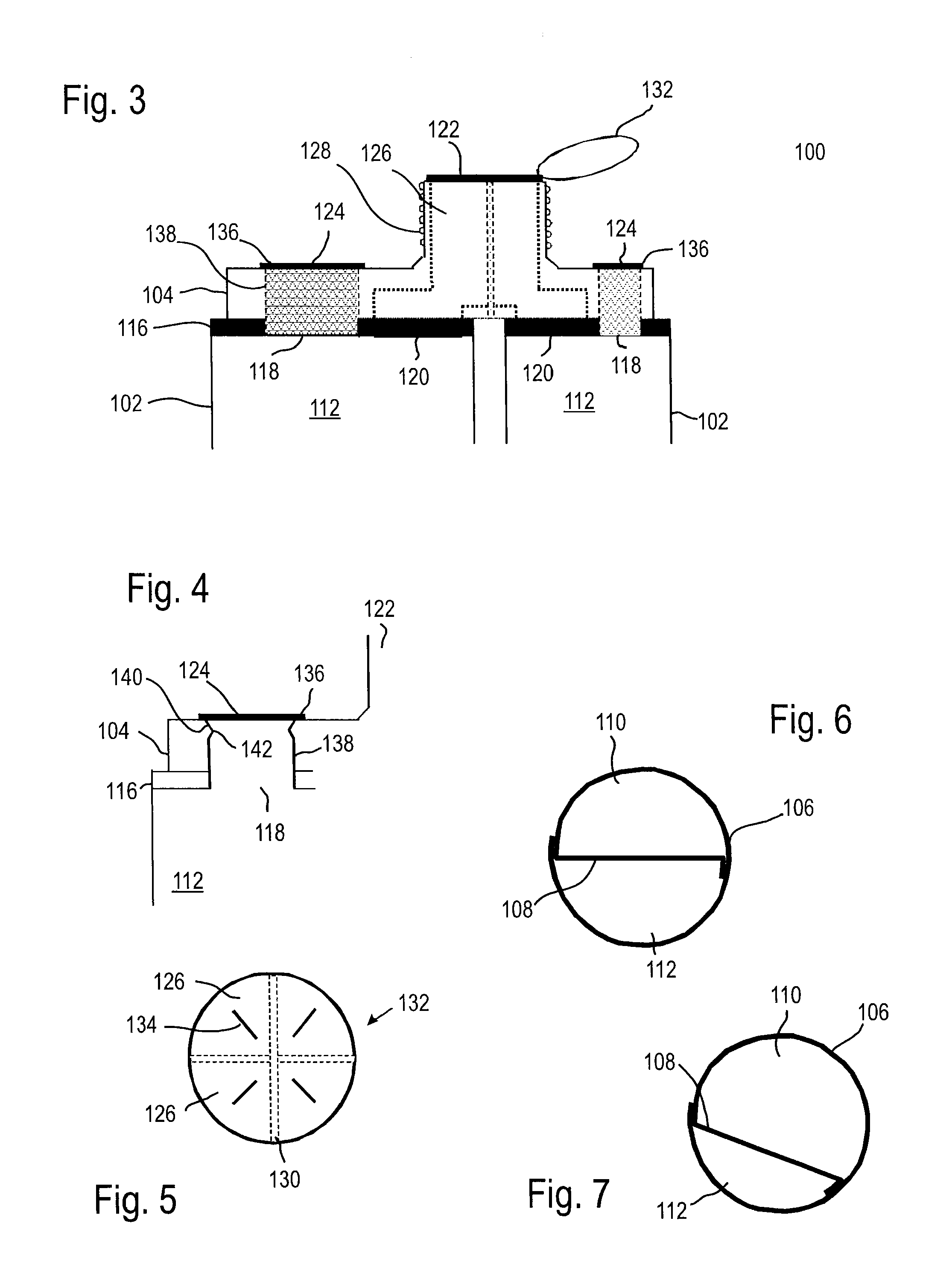
[0064]FIG. 1 shows a foil cartridge 100 in accordance with a first embodiment. The foil cartridge 100 in this case includes two foil reservoirs 102 as well as a head section 104 (see FIG. 3). The head section 104 is connected on an upper axial end to each of the two foil reservoirs 102 that are arranged next to each other.

[0065]One of the foil reservoirs 102 is depicted in greater detail in FIG. 2. A first, outer foil tube 106 is subdivided by a partition 108 (see FIGS. 6 and 7) into two parallel chambers 110, 112 that are separated from each other in the axial direction A. As FIGS. 6 and 7 show, the two chambers 110, 112 may be configured to be the same size or different sizes, which is achieved by the arrangement of the partition 108. Instead of a single partition 108, several partitions 108 could also be provided, which may extend in any desired manner through the cross-section of the foil tube 106.

[0066]The foil tube 106 and the partition 108 in FIGS. 6 and 7 are fabricated of a...

Example

[0091]A second embodiment of a foil cartridge 200 is depicted in FIGS. 8 to 12.

[0092]The reference numbers already used are retained for components that are identical to those of the first embodiment.

[0093]In this case, the separate chambers 110, 112 and 113 are realized by a second foil tube 206 being inserted into the first foil tube 106. In addition, as in the first embodiment, another partition 108 is provided here, which is located between the wall of the first foil tube 106 and that of the second foil tube 206 so that three chambers are formed overall. It would also be possible to provide several second foil tubes 206 or to further subdivide these with partitions.

[0094]As in the first embodiment, each of the chambers 110, 112, 113 is assigned a first opening 118 in the cover 216.

[0095]This arrangement applies to both foil reservoirs 202 (see FIG. 8).

[0096]In contrast to the first embodiment, in this case separate discharge openings are not provided. Correspondingly, the channe...

Example

[0100]FIGS. 13 to 16 show a third embodiment of a foil cartridge 300.

[0101]In contrast to the embodiments described so far, in this case first the foil reservoir 302 is filled before the head section 304 is fastened on the cover 316. The configuration and division of the two foil reservoirs 302 corresponds essentially to that of the first embodiment.

[0102]The head section 304 does not have any further openings besides the outlet opening 122. When the foil cartridge 300 is produced, first the foil reservoir 302 is fabricated. This is filled through the first openings 118, wherein the edge of the openings 118 may be configured in a manner similar to the above-described edge of the opening 124 with a conical taper and a sealing lip (see FIG. 20). After the chambers 110, 112 have been completely filled, the first openings 118 are sealed with closures 340. The closures 340 in this case are configured in the form of a foil having a weakened zone 342, as depicted schematically in FIG. 15. ...


PUM


Abstract

A foil cartridge is disclosed. The foil cartridge has a foil tube enclosing at least one chamber in the circumferential direction and a cover separate from the foil tube. The cover closes an axial end of the foil tube. At least one first opening is configured in the cover for each chamber, through which opening the chamber may be filled with a filling material. A closure is provided, which seals the first opening. To produce the foil cartridge, the chamber is established by connecting the cover with the foil tube. Then the chamber is filled with a filling material through the first opening in the cover and the first opening is sealed.

Description

[0001]This application claims the priority of German Patent Document No. 10 2011 007 475.9, filed Apr. 15, 2011, the disclosure of which is expressly incorporated by reference herein.BACKGROUND AND SUMMARY OF THE INVENTION[0002]The invention relates to a foil cartridge as well as a method for producing a foil cartridge.[0003]Foil cartridges having one or more chambers containing chemical compounds such as putty compounds, sealants or adhesive compounds are known. This type of foil cartridge is used in a cartridge holder of a dispensing device which is used to apply the chemical compounds to the desired location.[0004]The use of foil cartridges in which the chamber is essentially formed by a foil tube is beneficial because empty cartridges may be disposed of without great expense and without requiring a lot of space. For example, it is known from German Patent Document No. DE 295 01 255 U1 that the chamber may be created by combining the two ends of the foil bag into a “ponytail,” wh...

Claims


Application Information

Patent Timeline
IPC IPC(8): B65D35/10B65B43/00B65D35/22
CPCB65B3/16B65B39/12B65D81/3261B65D81/3272B65B2230/02B65B43/00B65D35/10B65D35/22B65D83/0072
Inventor WILLNER, RALFKLEINHANS, GOTTFRIEDBAESSLER, ARMIN
Owner HILTI AG
Why Eureka
Try Eureka