Method for treating powdery particles

Inactive Publication Date: 2005-06-02
VALMET TECHNOLOGIES INC
3 Cites 3 Cited by

AI-Extracted Technical Summary

Problems solved by technology

If the particles of the dry powder do not adhere properly to a substrate it causes an unev...

Benefits of technology

[0018] The pre-charging of the particles of the coating powder can be made either when the particles are brought at the final electric field or before bringing them into the final electric field. The aim of the pre-charging is to obtain...

Abstract

A method for preliminary treatment of particles of a powder in a dry surface treatment process before applying the powder particles on a surface of a substrate by utilizing an electric field created by electrodes. The Electrodes are located at opposite sides of the substrate in such a way that at least one first electrode is located at the side of the substrate to be coated, and at least one second electrode is located at the opposites side of the substrate. The particles of the powder are pre-charged before bringing them into the electric field.

Application Domain

Liquid spraying plantsPretreated surfaces +9

Technology Topic

Electric fieldPre-charge +2

Image

  • Method for treating powdery particles
  • Method for treating powdery particles
  • Method for treating powdery particles

Examples

  • Experimental program(1)

Example

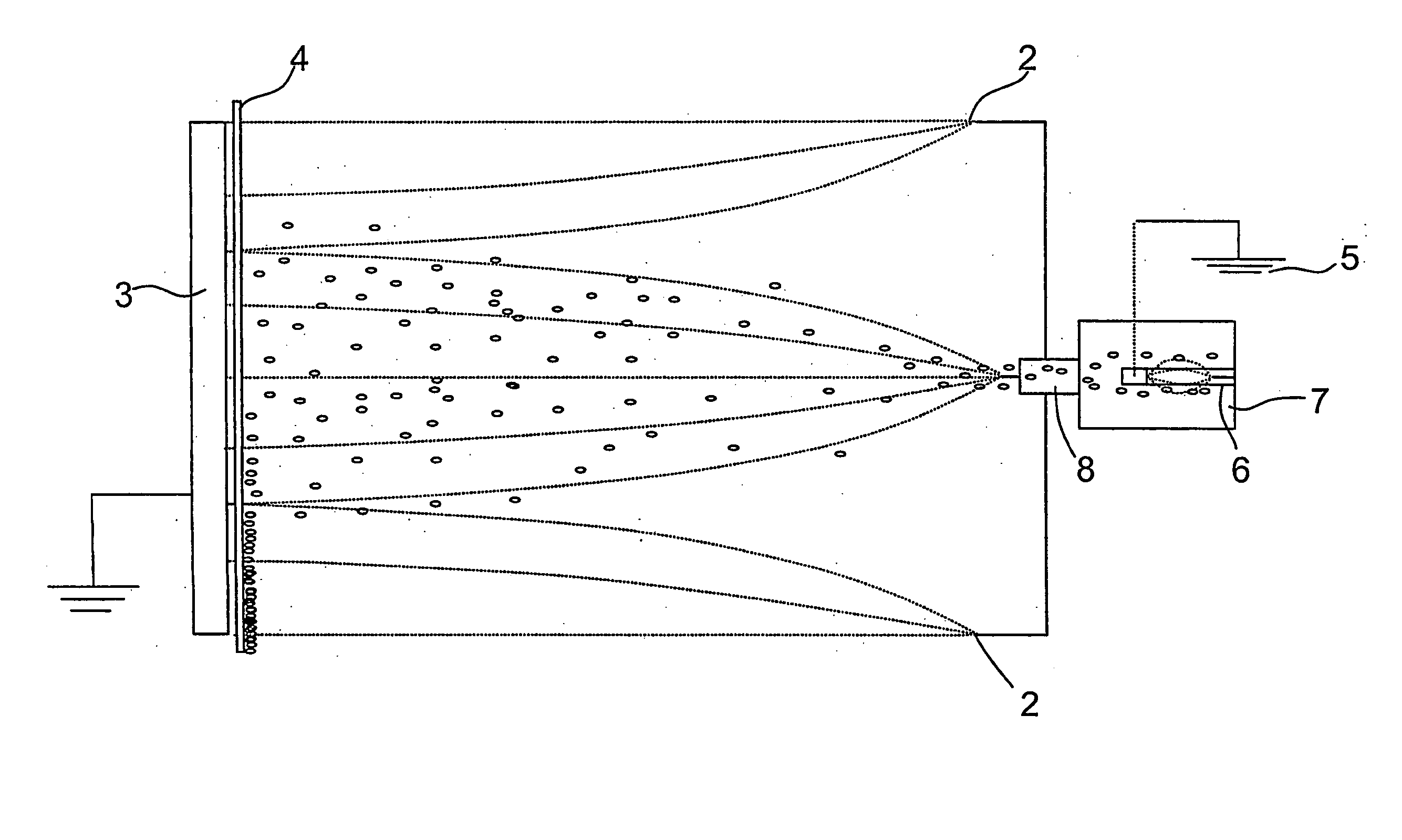
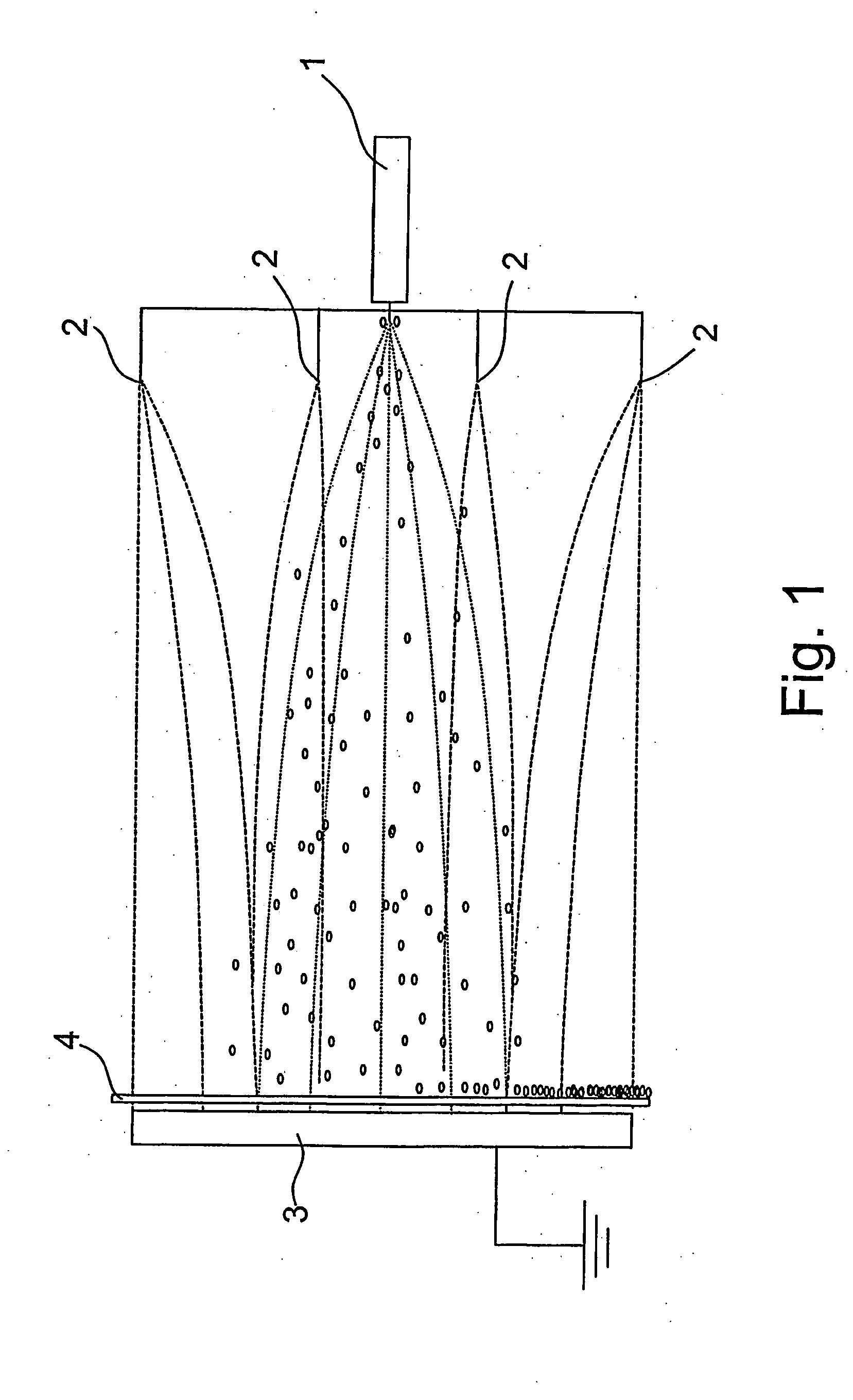
[0025] According to FIG. 1, a dry powder is led to a charging electrode 1 comprising a feeding nozzle. Particles of the dry powder are charged by the charging electrode 1. The charging electrode is located farther from other electrodes 2 so that the particles are pre-charged when they enter to the final electric field formed by the corona charging electrodes 1, 2 and a grounding electrode 3. The pre-charged particles are blown towards a substrate 4 to be coated. The substrate 4 is preferably in a web form. The grounding electrode 3 can be a stationary platy electrode, or it can be a roll rotating about its axis. The rotating roll is a preferred choice.
[0026] According to FIG. 2, a dry powder is led to a first electric field and after that to a second electric field. Particles of the dry powder are charged in a charging unit 7 comprising a corona charging electrode 6, a grounding electrode 5, and a feeding nozzle 8. The particles are pre-charged in the first electric field created in the charging unit 7 before entering to the second electric field formed by the corona charging electrodes 2 and a grounding electrode 3. The pre-charged particles are blown towards a substrate 4 to be coated. As in the embodiment shown in FIG. 1, the remarks concerning the form of the substrate 4 and the preferred grounding electrode 3 are also valid in this embodiment.
[0027] The invention is not restricted to the description above, but the invention may vary within the scope of the claims.

PUM

PropertyMeasurementUnit
Time1.0s
Electric field
tensileMPa
Particle sizePa
strength10

Description & Claims & Application Information

We can also present the details of the Description, Claims and Application information to help users get a comprehensive understanding of the technical details of the patent, such as background art, summary of invention, brief description of drawings, description of embodiments, and other original content. On the other hand, users can also determine the specific scope of protection of the technology through the list of claims; as well as understand the changes in the life cycle of the technology with the presentation of the patent timeline. Login to view more.

Similar technology patents

2-piperazinone-1-acetic acid derivatives and their use

InactiveUS6242600B1High potencyLong periodOrganic chemistryAdhesion processDisease
Owner:TAKEDA PHARMACEUTICA CO LTD

Spi interface enhanced flash chip and chip packaging method

ActiveUS20150186067A1High design complexityLong periodInput/output to record carriersSolid-state devicesFlash memory
Owner:GIGADEVICE SEMICON (BEIJING) INC

Classification and recommendation of technical efficacy words

Why Eureka
Try Eureka