Algorithm and implementation system for measuring impedance in the d-q domain

Active Publication Date: 2013-04-25
THE BOEING CO +1
View PDF4 Cites 22 Cited by
  • Summary
  • Abstract
  • Description
  • Claims
  • Application Information

AI Technical Summary

Benefits of technology

[0011]It is therefore an object of the present invention to provide a an apparatus for measuring impedance of respective phases of a multi-phas

Problems solved by technology

However, provision of such regulation causes additional phenomena that have not been previously observed or considered to be of importance, including but not limited to issues of stability.
As is well recognized in the art, negative impedance can result in instabilities and possibly oscillatory behavior of the circuit with detrimental effects to the system where they operate.
While the extensive power grid can tolerate many of these behaviors since the effect of converter behavior is small compared to the size of the system, such behaviors cannot be tolerated by smaller systems which have their own, relatively small capacity power source and are not connected to the effectively infinite power grid.
Other examples of circumstances where unstable behavior may occur are instances where electrical loads are connected through equipment such as frequency changers (AC/AC converters), AC/DC converters and other types of hardware.
Vehicular systems also operate at higher line frequencies than the line frequencies traditionally used fo

Method used


Image

  • Algorithm and implementation system for measuring impedance in the d-q domain
  • Algorithm and implementation system for measuring impedance in the d-q domain
  • Algorithm and implementation system for measuring impedance in the d-q domain

Examples


Embodiment Construction

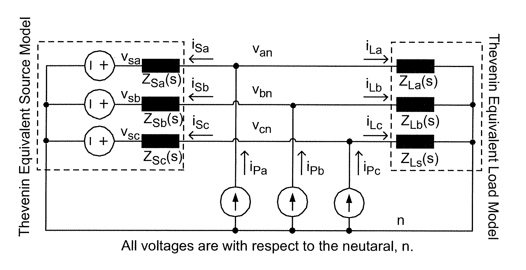
[0025]Referring now to the drawings, and more particularly to FIG. 1, there is shown a schematic diagram of a generalized there-phase power system having an interface between a source and a load. It should be understood that any juncture between portions of a power converter system will provide an interface between “upstream” circuits and “downstream” circuits and that the former functions as a source for the latter and the latter may be considered as a load for the former. In the schematic diagram of FIG. 1, current sources iPa, iPb and iPc are capable of injecting current into and thus perturbing the respective phases of the power converter circuit. The source and load impedances (e.g. Zsa(s) and Zla(s) for phase a) of respective phases can thus be derived from the resulting voltages and upstream and downstream currents (e.g. voltage van, vsa and vLa and currents isa and iLa for phase A).

[0026]The above-incorporated U.S. patent application Ser. No. 13 / 608,213 discloses a simplifie...


PUM


Abstract

A controller and infrastructure for an impedance analyzer measures responses to perturbations to respective phases of a multi-phase system at an interface between stages thereof (which may be considered as a source and load in regard to each other), such as a multi-phase electrical power system, to determine a transfer function for each phase of the multi-phase system from which the impedance of each of the source and load can be calculated, particularly for assessing the stability of the multi-phase system.

Description

CROSS-REFERENCE TO RELATED APPLICATIONS[0001]This application claims benefit of priority of U.S. Provisional Applications 61 / 532,588 filed Sep. 9, 2011 and 61 / 535,398, filed Sep. 16, 2011, both of which are hereby incorporated by reference in their entireties. This application is also related to U.S. patent application Ser. No. 13 / 608,213, filed Sep. 10, 2012, which is also incorporated by reference in its entirety.FIELD OF THE INVENTION[0002]The present invention generally relates to a methodology and apparatus for direct measurement of impedance of an AC power source and power converter and, more particularly, to measurement of impedance of portions of a power circuit at interfaces therebetween and which may be time-varying and / or non-linear; which measurements may be conducted on-line while the power circuit is delivering power to a load.BACKGROUND OF THE INVENTION[0003]Traditionally, electrical power has been produced by large, geographically separated facilities and transmitted...

Claims


Application Information

Patent Timeline
IPC IPC(8): G01R27/02
CPCG01R27/02H02J3/38G01R27/16G01R27/14
Inventor FRANCIS, GERALDBURGOS, ROLANDOBOROYEVICH, DUSHANWANG, FREDSHEN, ZHIYUMATTAVELLI, PAOLOKARIMI, KAMIARFU, SHEAU-WEI JOHNNY
Owner THE BOEING CO
Why Eureka
Try Eureka