Multicompartment layered and stackable microfluidic bioreactors and applications of same

a microfluidic bioreactor and multi-component technology, applied in the field of microfluidic systems, can solve the problems of large fluid volume, inability to support all the cell types involved in bbb formation, and inability to provide shear force, etc., and achieve the effect of disassembly for cellular analysis

Active Publication Date: 2018-11-15
VANDERBILT UNIV
View PDF0 Cites 19 Cited by
  • Summary
  • Abstract
  • Description
  • Claims
  • Application Information

AI Technical Summary

Benefits of technology

[0018]In certain embodiments, the base for each layer supports the membrane filter that separates two chambers. The thin base is supported on its edges by a surrounding, thicker and stiffer frame. The lateral dimensions of the frame for each successive layer are such that the frame for the lowest layer is largest, and the frame for successive upper layers is progressively reduced so that the upper layers nest inside the lower ones. In some embodiments, the set of nested layers can be clamped together to eliminate leaks from the channels of each layer and allow the layers to be disassembled for cellular analysis.

Problems solved by technology

However, this critical and complex structure remains difficult to model in vitro.
Many existing in vitro models either fail to support all the cell types involved in BBB formation and / or do not provide the shear forces created by flow necessary for mature tight junction formation.
While the transwell BBB with endothelial cells and astrocytes is a standard in the pharmaceutical industry, its shortcomings include the lack of shear-flow induced polarization of the endothelial cells; large, physiologically unrealistic fluid volumes; difficulty in supporting more than two cell types; and the inability to use electrical recordings to monitor neural activity in situ.
The ability of the cells in the insert to sense the signals from cells in the well is compromised by the dilution of signaling molecules and metabolites by the large fluid volumes in both the well and the insert.
Therefore, a heretofore unaddressed need exists in the art to address the aforementioned deficiencies and inadequacies.

Method used


Image

  • Multicompartment layered and stackable microfluidic bioreactors and applications of same
  • Multicompartment layered and stackable microfluidic bioreactors and applications of same
  • Multicompartment layered and stackable microfluidic bioreactors and applications of same

Examples


example 1

A Wet-Assembleable Layered NVU Bioreactor

[0179]In certain embodiments, one NVU design uses permanently bonded PDMS layers that must be completely assembled prior to cell seeding, thus precluding disassembly for tissue acquisition and additional examinations for proteomic or genetic analysis such as RNAseq. Furthermore, the NVU is useful only if all cell types within all chambers achieve the required cell confluence and viability on the same timescale.

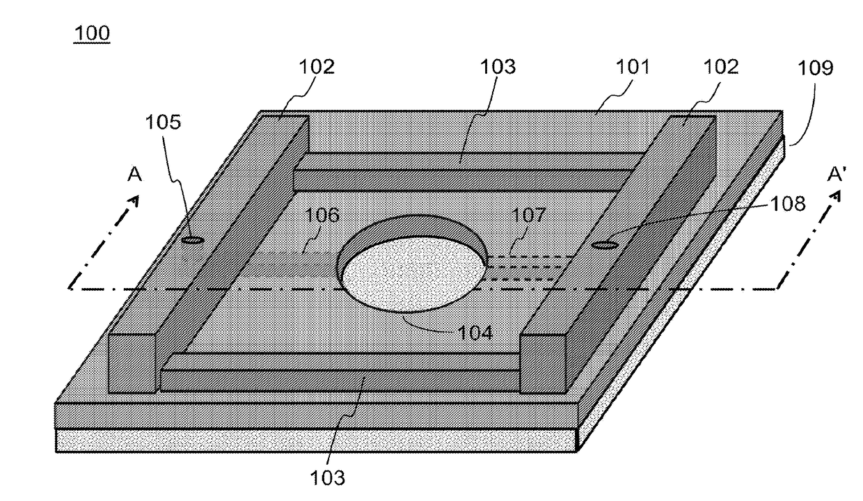
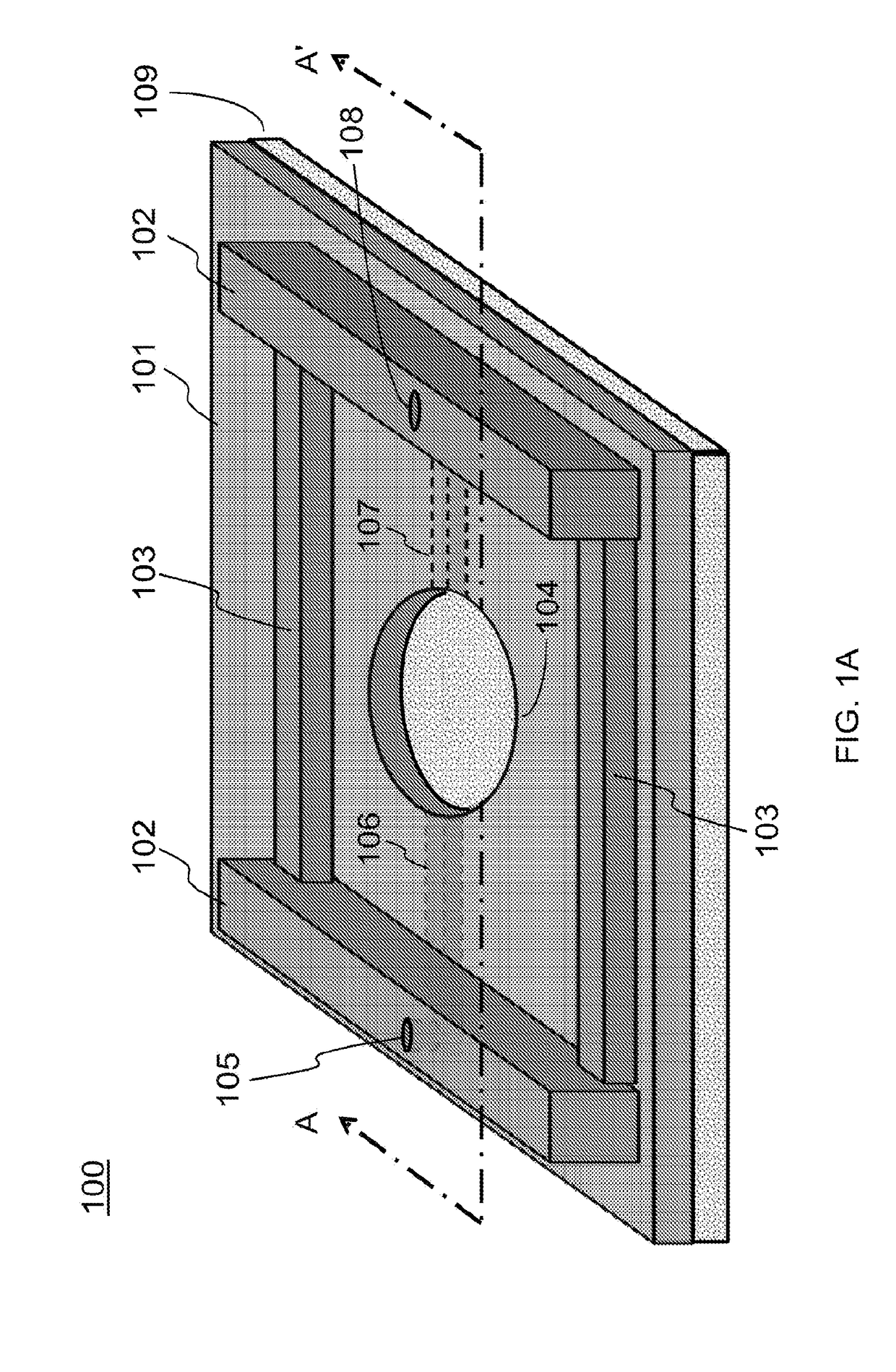
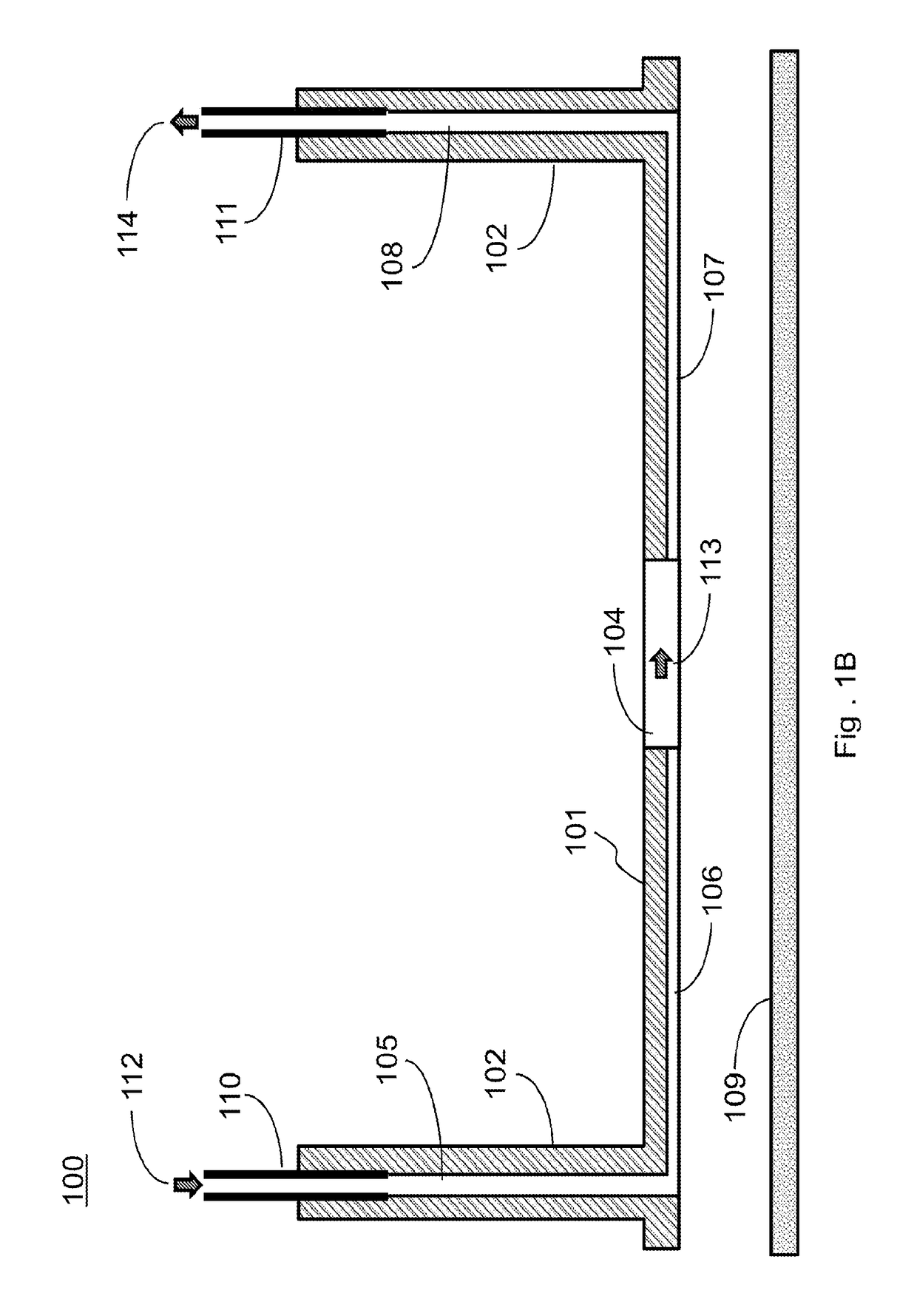
[0180]As an improvement of the above NVU, the present invention provides a design by moving from PDMS to COC or another material. The design includes a stackable planar device that can be assembled into an NVU after cell seeding and maturation, creating four 300 μm-thick chambers (vascular, neuronal, CSF, and vascular, bottom-to-top) with glass coverslips sealing the bottommost and topmost chambers.

[0181]In this improved design, a clamped bioreactor is provided with a brass clamp providing the force to keep multiple layers in fluid-tigh...

example 2

Generation of Functionally Validated Human Cortical Neurons for the NVU-IOM System

[0184]Because of the recognized differences between human and mouse / rat / dog physiology, there is general recognition that human cells need to be incorporated as early as possible in the drug discovery pipeline. However, there are severe limitations in the commercial supply of human cortical neurons. Therefore, in certain embodiments, a NVU is provided with incorporated human glutamatergic dorsal forebrain (cortical pyramidal) neurons and co-differentiating astrocytes.

[0185]De-identified human induced pluripotent stem cells (iPSCs) derived from control subjects, previously published by the Bowman and Neely group, are used to generate the neuronal / glial cultures. A dual SMAD inhibition monolayer method is used which exposes iPSCs for the first 11 days to LDN 193189 and SB431542, inhibitors of the Bone Morphogenetic Protein (BMP) and Tumor Growth Factor-β1 (TGF-β1) pathways, respectively, to induce ontoge...

example 3

Electrophysiological Validation of Human Cortiacl Neurons in the Stackable Layered NVU

[0189]In certain embodiments, to confirm cortical neuron functionality, their electrophysiological activity is recorded using a high-resolution CMOS MEA already been proven to capture spatiotemporal signaling dynamics.

[0190]As preliminary data, a 3Brain MEA was used to confirm that the iPSC-derived neurons of the present invention are electrically active and respond pharmacologically. It is observed that spontaneous activity of >90 day cortical neurons that was completely and reversibly inhibited by tetrodoxin and partially inhibited by NBQX).

[0191]In this example, a subset of each batch of cortical neurons differentiated for 90 days is plated onto a high resolution CMOS (Complementary Metal Oxide Semiconductor) MEA (3Brain GmbH, Landquart, Switzerland) coated with poly-L-ornithine and laminin. The array contains 4096 independently addressable 21 μm×21 μm recording electrodes pitched at 42 μm and s...


PUM

PropertyMeasurementUnit
heightaaaaaaaaaa
heightaaaaaaaaaa
heightaaaaaaaaaa

Abstract

In certain aspects of the invention, a stackable device includes multiple elements stacked sequentially. A chamber is formed in each of the elements or between adjacent two of the elements, and each chamber is in fluid communication with an input channel and an output channel. The chambers are aligned with each other, and adjacent two chambers are separated from each other by a membrane. In certain aspects of the invention, a system includes at least one stackable device, each stackable device having multiple chambers; and at least one of a perfusion controller, a microformulator, and a microclinical analyzer in fluid communication with the at least one stackable device. In other aspects of the invention, the use of four microformulators, electrodes and an impedance analyzer can measure the impedance spectrum of each barrier in a multi-transwell plate.

Description

CROSS-REFERENCE TO RELATED PATENT APPLICATIONS[0001]This PCT application claims priority to and the benefit of, U.S. Provisional Patent Application Ser. No. 62 / 259,327, filed Nov. 24, 2015. The entire disclosure of the above-identified application is incorporated herein by reference.[0002]This PCT application also is a continuation-in-part application of U.S. application Ser. No. 15 / 191,092, filed Jun. 23, 2016; Ser. No. 14 / 651,174, filed Jun. 10, 2015; Ser. No. 14 / 646,300, filed May 20, 2015; Ser. No. 14 / 363,074, filed Jun. 5, 2014; and Ser. No. 13 / 877,925, filed Jul. 16, 2013. The entire disclosure of each of the above-identified applications is incorporated herein by reference.STATEMENT OF FEDERALLY SPONSORED RESEARCH[0003]The present invention was made with government support under Contract No. 1UH2-TR000491-01, awarded by the National Institutes of Health. The government has certain rights in the invention.[0004]Some references, which may include patents, patent applications, a...

Claims


Application Information

Patent Timeline
Patent Type & Authority Applications(United States)
IPC IPC(8): B01L3/00B01L9/00C12M3/06C12M1/00G01N33/543G01N35/08
CPCB01L3/502715B01L3/502707B01L9/00C12M23/16C12M29/10G01N33/54366G01N35/08B01L2300/0816B01L2300/0874B01L2400/0415B01L2400/0472B01L2400/0487B01L3/50255B01L2300/0887C12M23/34C12M29/04G01N27/026G01N27/00
Inventor WIKSWO, JOHN P.MARKOV, DMITRY A.REISERER, RONALD S.
Owner VANDERBILT UNIV
Why Eureka
Try Eureka