Eureka AIR delivers breakthrough ideas for toughest innovation challenges, trusted by R&D personnel around the world.

System and method for eliminating process gas leak in a solids delivery system

Active Publication Date: 2008-06-19
AIR PROD & CHEM INC
View PDF29 Cites 26 Cited by
  • Summary
  • Abstract
  • Description
  • Claims
  • Application Information

AI Technical Summary

Benefits of technology

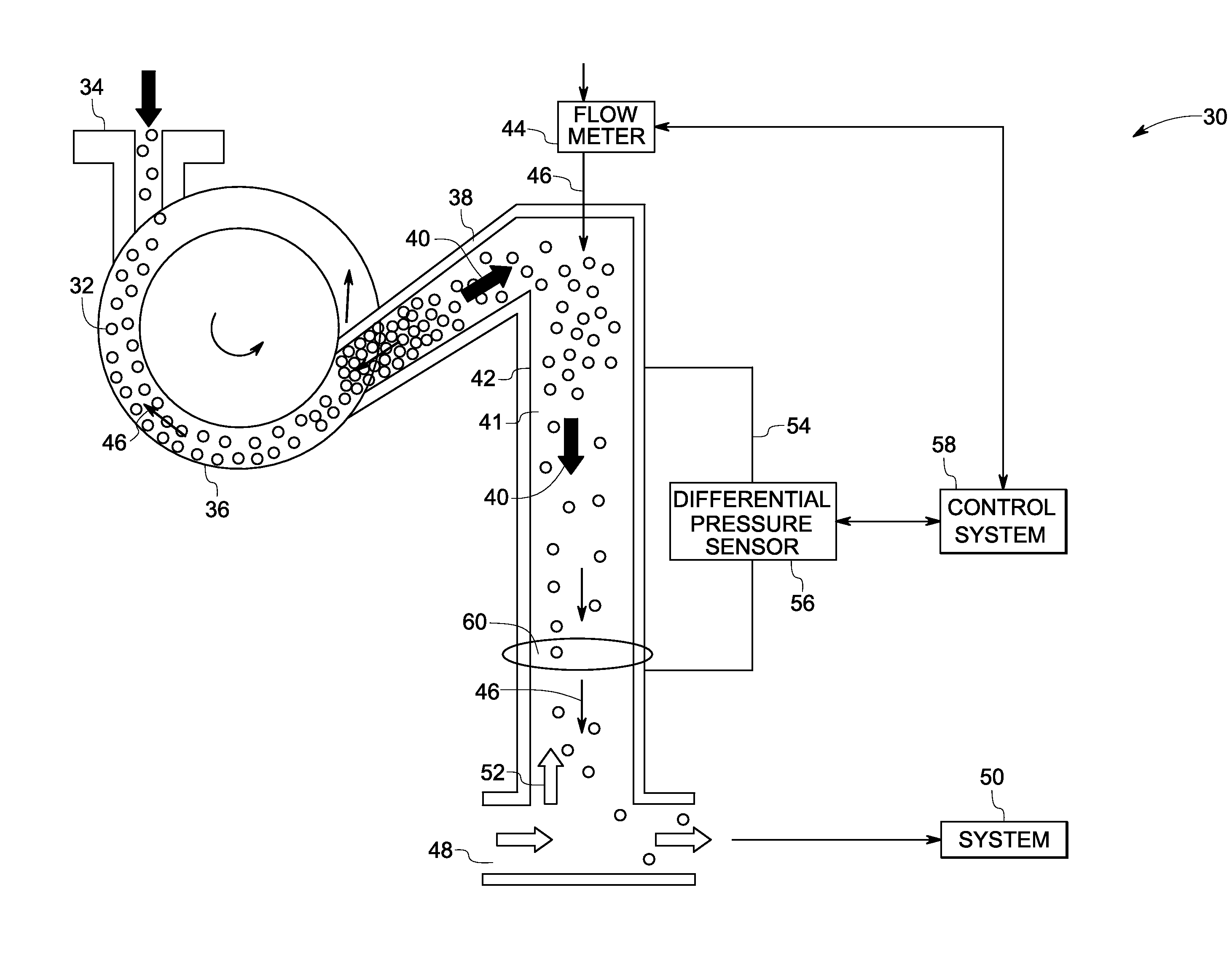
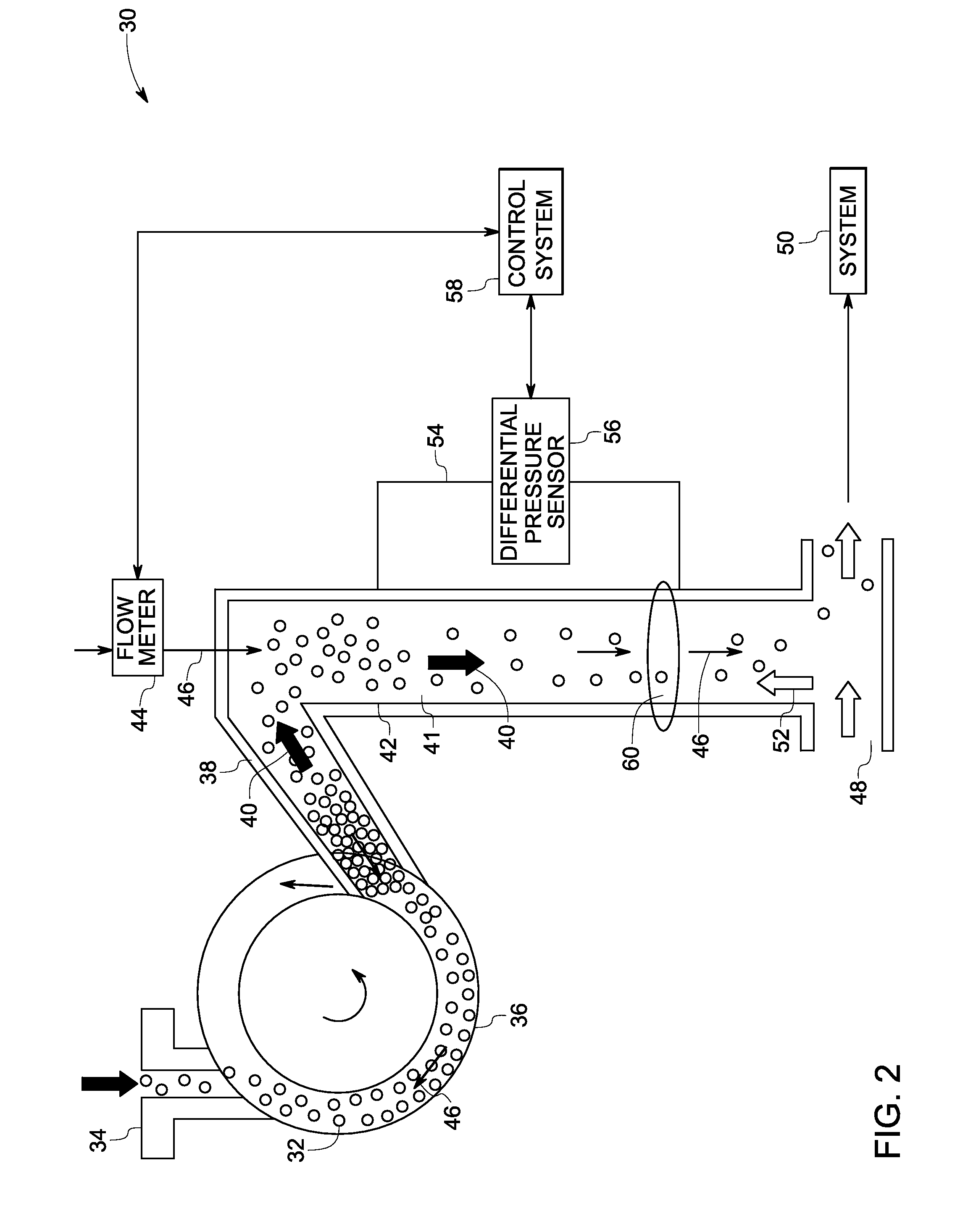
[0007]In accordance with another aspect of the invention, a method for eliminating leakage of process gas in a solids delivery system is provided. The method includes transporting a particulate material from an inlet to an outlet via a bulk solids pump. The method also includes forming a seal of the particulate material in the outlet. The method also includes passing a buffer gas through a channel at a pressure sufficient to limit the backflow of a process gas. The method further includes sensing a flow rate of the buffer gas via a flow meter. The method also includes maintaining a positive differential in pressure between the buffer gas and the process gas via at least two pressure sensors or one differential pressure sensor.

Problems solved by technology

While bulk solids pumps, offer several benefits, there still exists a potential for process gas leakage back through such pumps during operation.
The leak may pose undesirable safety and operational concerns since process gas may be sufficiently combustible, reactive, corrosive, or toxic to create hazardous conditions if it mixes with gases or the atmospheres upstream of the pump, including ambient air.
The process gas that is hot or cold beyond a desirable limit may also cause damage while entering regions of the pump and upstream system that are not designed for such conditions.
Further, the process gas may contain species that could condense onto the solids in an upstream equipment, reacting with the solids or wetting the solids thus causing problems including with solids flow and plugging.
Even in absence of the foregoing problems, the loss of process gas back through the rotary solids pump may be undesirable for cost reasons.
Further, such gas leakage unchecked could produce instabilities in the solids flow to and in the operation of a process or system, leading to other operational, equipment, and safety issues.
A malfunction in a rotary type bulk solids pump also may lead to a large and uncontrolled leak of process gas that may be combustible, reactive, corrosive or toxic.

Method used


Image

  • System and method for eliminating process gas leak in a solids delivery system
  • System and method for eliminating process gas leak in a solids delivery system
  • System and method for eliminating process gas leak in a solids delivery system

Examples


Embodiment Construction

[0012]As discussed in detail below, embodiments of the present invention include a system for eliminating gas leak in a solids delivery system and method for the same. As used herein, the term “gas leak” refers to process gas that is leaked into the solids delivery system from a downstream process or system, or from a gas that is introduced into the solids delivery system downstream of the buffer gas such as, but not limited to, a fluidizing gas, a pneumatic conveyor carrier gas, a pressurizing gas, as one or more separate streams. The solids delivery system includes a conveyance apparatus that transports and pressurizes particulate material for a downstream process or system such as, but not limited to, a gasifier in a gasification process to produce a hot synthesis gas product. A non-limiting example of the conveyance apparatus is a bulk solids pump.

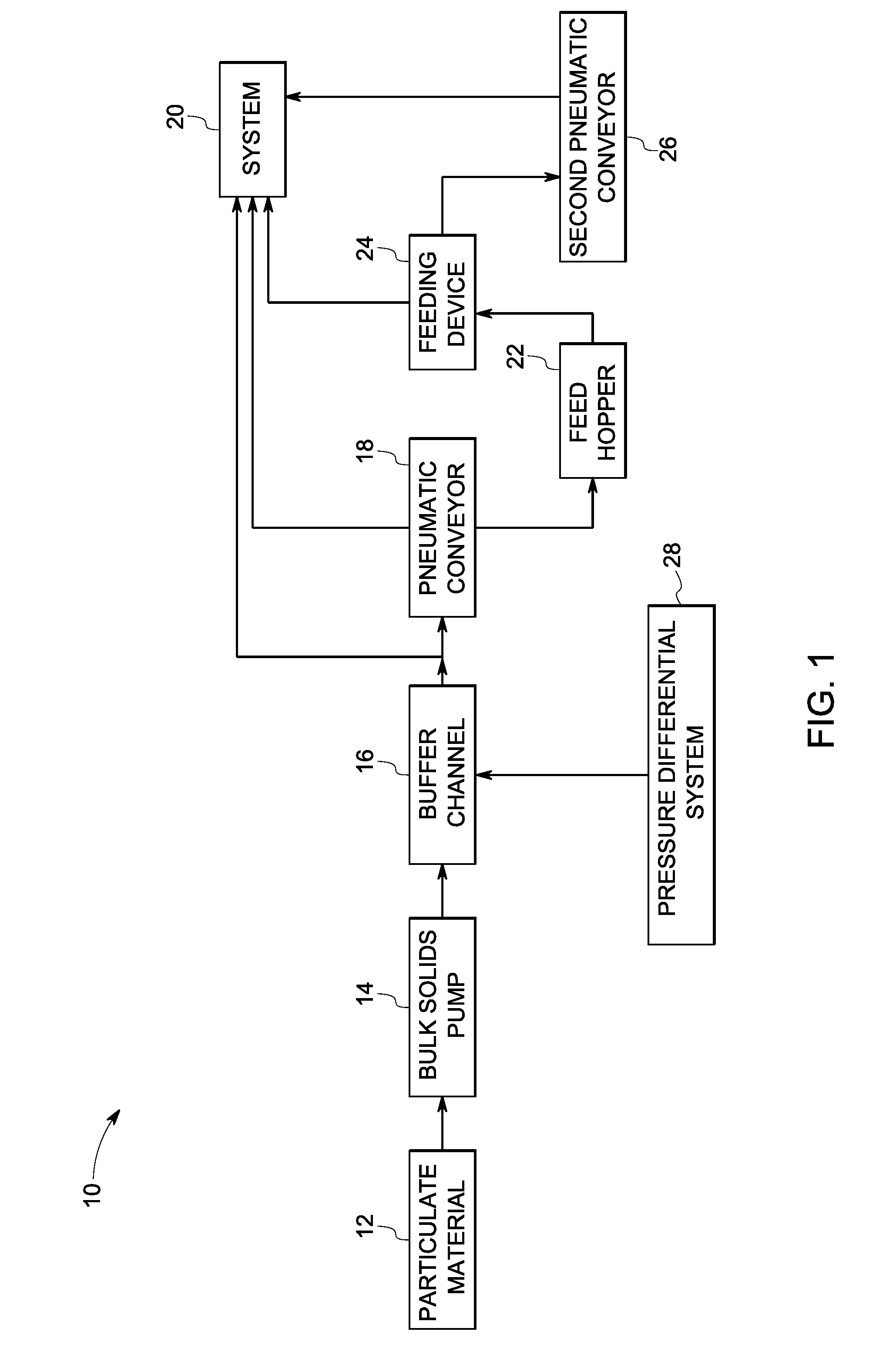
[0013]FIG. 1 is a block diagram representation of a system 10 for eliminating process gas leak in a solids delivery system. The solid...


PUM


Abstract

A system for controlling gas leakage in a solids delivery system is provided. The system includes a bulk solids pump comprising an inlet for a particulate material and an outlet for discharge of said particulate material. The system also includes a buffer gas channel configured to impede backflow of process gas into the bulk solids pump, such as from a downstream system or process. The system further includes a pressure differential system configured to control a flow rate of the buffer gas and maintain a positive differential in pressure between the buffer gas and the process gas.

Description

BACKGROUND[0001]The invention relates generally to solids delivery systems for feeding solids into pressurized systems, more specifically to solids delivery systems utilizing bulk solids pumps, such as a rotary solids pump, to feed solids to a process or system operating at elevated pressure.[0002]A wide variety of equipment has been used to pressurize, transport and feed particulate material such as, but not limited to, solid fuels, minerals, chemicals, fillers, polymers, and other dry materials handled in solid, particle form to chemical or thermal conversion processes or other systems, such as storage systems, operating at elevated pressures. Some non-limiting examples of such equipment include lock-hoppers, screw-type feeders, piston feeders, and various combinations thereof.[0003]Bulk solids pumps can be an attractive means for pressurizing, transporting or feeding particulate materials into such processes or systems, either alone or in combination with other such pressurizing,...

Claims


Application Information

Patent Timeline
IPC IPC(8): B65G53/66B65G51/16B65G53/58B65G53/00
CPCB65G53/48B65G2207/40B65G2203/042B65G53/66
Inventor LIVINGOOD, WILLIAM COOKSTEVENSON, JOHN SAUNDERSLONGTIN, RANDY SCOTT
Owner AIR PROD & CHEM INC
Why Eureka
Eureka Blog
Learn More