Fuel Injector, a Fuel Injector Assembly and an Associated Method

Active Publication Date: 2017-05-04
CATERPILLAR INC
View PDF9 Cites 0 Cited by
  • Summary
  • Abstract
  • Description
  • Claims
  • Application Information

AI Technical Summary

Benefits of technology

[0012]the cleaning fluid supply passage being in fluid communication with the second end of the bore and configured to supply a pressurised cleaning fluid to the second end of th

Problems solved by technology

A problem with fuel injectors is that they may need to be cleaned periodically to remove combustion products which, if left, might reduce fuel flow and may ultimately lead to blockage of the fuel injector.
Another problem which may occur with fuel injectors is where deposits of the fuel accumulate within the fuel injector.
This may particularly be a probl

Method used


Image

  • Fuel Injector, a Fuel Injector Assembly and an Associated Method
  • Fuel Injector, a Fuel Injector Assembly and an Associated Method
  • Fuel Injector, a Fuel Injector Assembly and an Associated Method

Examples


Embodiment Construction

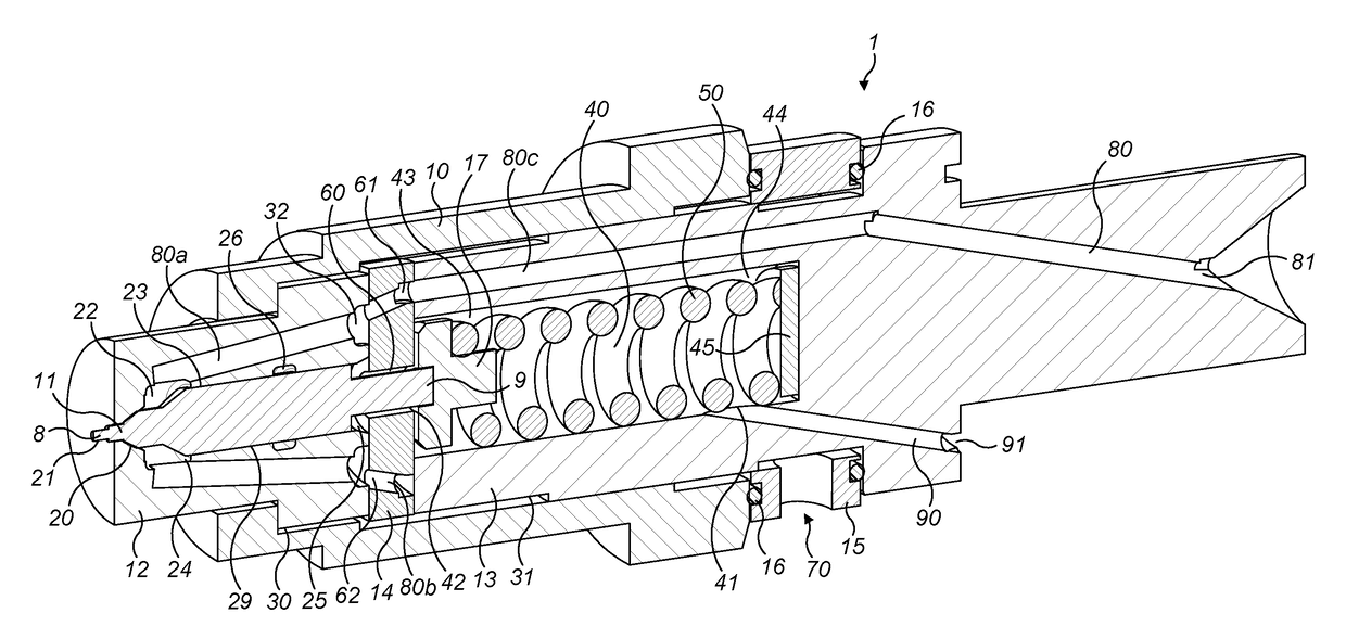
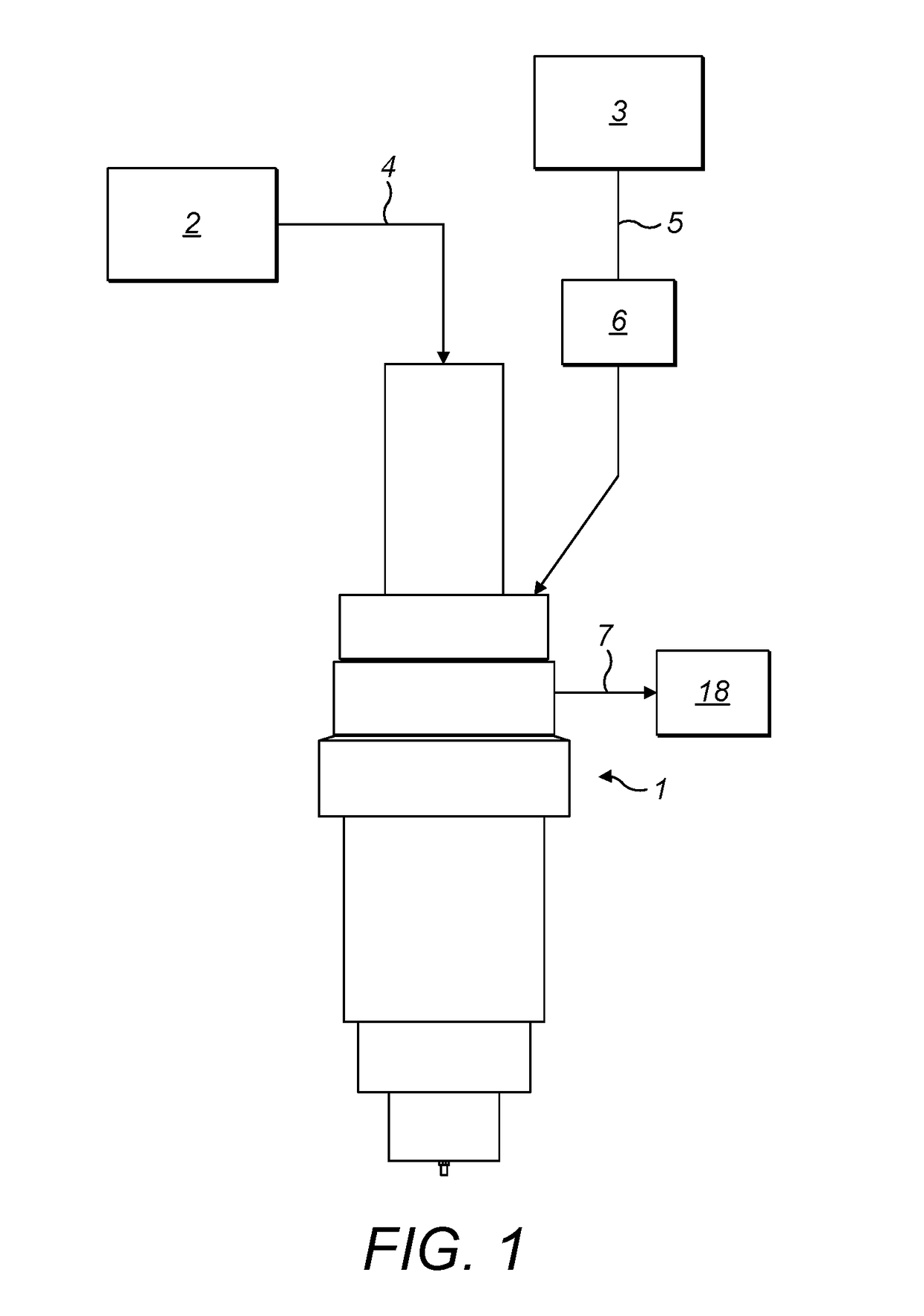
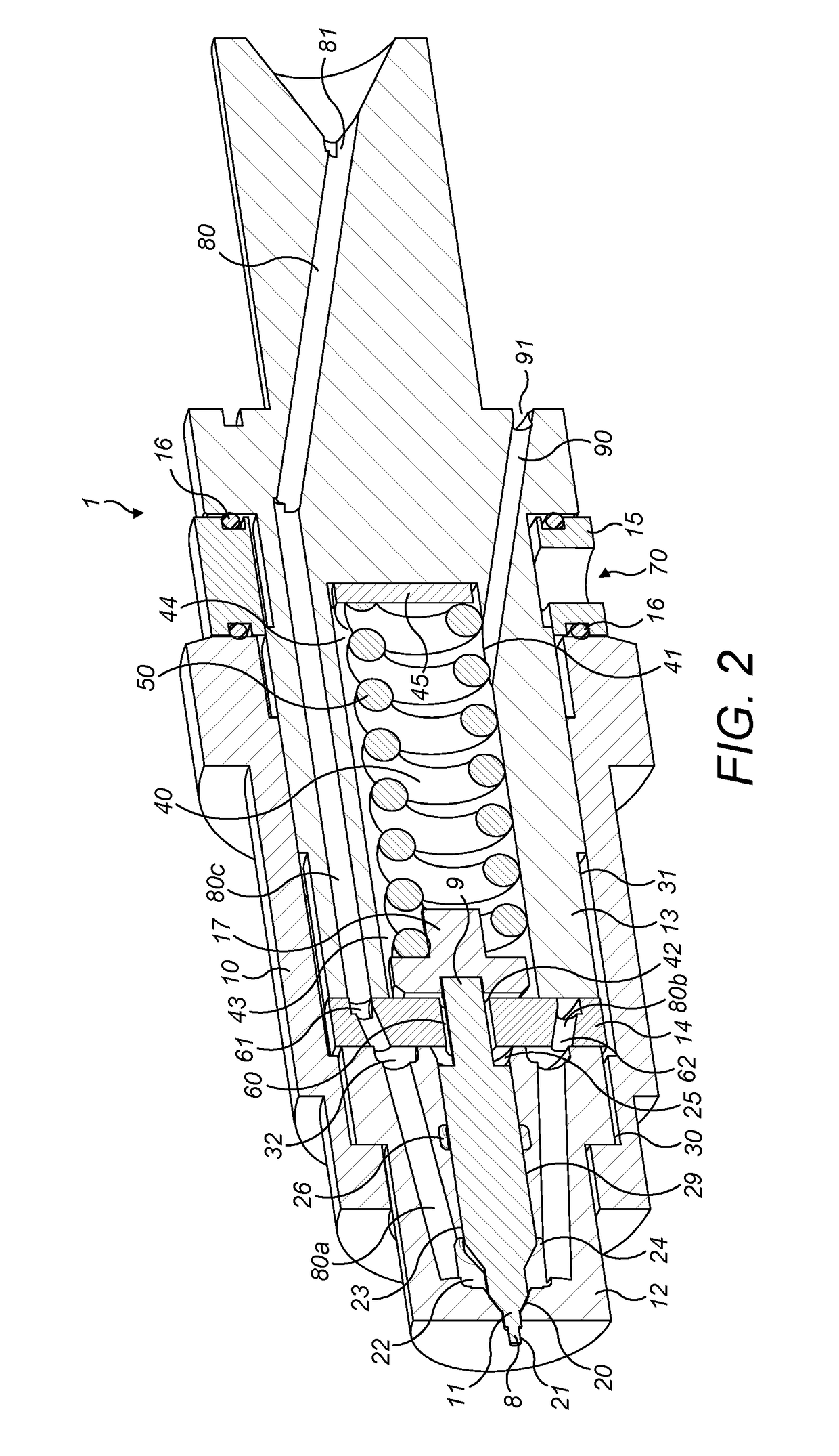
[0029]As illustrated in FIG. 1, a fuel injection assembly according to the present disclosure comprises a fuel injection pump 2, a cleaning fluid pump 3 and a fuel injector 1. The fuel injection assembly may be configured for use with an internal combustion engine, preferably a C.I. engine. The fuel injection pump 2 is connected to the fuel injector 1 by a fuel supply conduit 4. The fuel injection pump 2 may be integrated with the fuel injector 1 as a single component or may be a separate component. The fuel injection pump 2 may be driven off an elliptical cam to produce a cyclical increase and decrease in the pressure of the fuel supplied by the fuel injection pump 2 to the fuel supply conduit 4. The cleaning fluid pump 3 may be connected to the fuel injector 1 via a cleaning fluid sensor 6 by means of a cleaning fluid supply conduit 5. The cleaning fluid pump 3 may be integrated with the fuel injector 1 as a single component or may be a separate component. A fuel leakage conduit 7...


PUM


Abstract

A fuel injector (1) is provided which comprises a valve member (11), a valve member guide (12) and a spring chamber (40). Discharge of fuel out of a fuel injector outlet (21) is controlled by movement of the valve member (11) within a bore (23) of the valve member guide (12). The spring chamber (40) contains a biasing member (50), for example a compression spring, which biases the valve member (11) into contact with a valve seat (20) when in a closed configuration.
A fuel supply passage (80) is provided, which by-passes the spring chamber (40), to direct a flow of the fuel to an outlet chamber (22) of the fuel injector (1) and a cleaning fluid supply passage (90) is provided to supply a pressurised cleaning fluid to a second end (25) of the bore (23) to restrict leakage of the fuel from the outlet chamber (22) towards the second end (25) of the bore (23) along a clearance (29) extending between the valve member (11) and the valve member guide (12).

Description

TECHNICAL FIELD[0001]The disclosure relates to a fuel injector, a fuel injector assembly and an associated method of operation of the fuel injector assembly.BACKGROUND[0002]Internal combustion engines may be provided with a fuel injector in each cylinder of the internal combustion engine which operate to provide controlled delivery of fuel for combustion within the cylinder. Fuel injectors can be used for the direct or indirect injection of fuel into either a combustion chamber or an interconnecting pre-combustion chamber or a combustion air ducting of the internal combustion engine. Fuel injectors may be used in both compression ignition (C.I.) and spark ignition (S.I.) engines. Fuel injectors for C.I. engines normally operate at much higher pressures that those for S.I. engines.[0003]A problem with fuel injectors is that they may need to be cleaned periodically to remove combustion products which, if left, might reduce fuel flow and may ultimately lead to blockage of the fuel inje...

Claims


Application Information

Patent Timeline
IPC IPC(8): F02M65/00F02M61/04F02M63/00F02B77/04
CPCF02M65/008F02M63/0017F02M61/04F02B77/04F02M61/16F02M61/02F02M65/007F02M43/04
Inventor MAWHINNEY, GRAEMESTOCKNER, ALAN R.STARK, PAULMACK, DAVID
Owner CATERPILLAR INC
Why Eureka
Try Eureka