Inflatable ear mold connection system

a technology of ear molds and connection systems, which is applied in the field of ear pieces, can solve problems such as problems in the normal operation and handling of such ear molds, and achieve the effects of simple assembly, easy and simple refurbishment, and small effor

Inactive Publication Date: 2013-04-25
SIVANTOS PTE LTD
View PDF0 Cites 19 Cited by
  • Summary
  • Abstract
  • Description
  • Claims
  • Application Information

AI Technical Summary

Benefits of technology

This patent describes an improved design for an inflatable earpiece that can be easily placed in the ear canal and safely inflated or deflated without difficulty. It also has a simplified construction process and allows for easy replacement parts.

Problems solved by technology

The technical problem addressed in this patent text needs to be identified by a senior R&D person who can read it easily without adding any new information.

Method used


Image

  • Inflatable ear mold connection system
  • Inflatable ear mold connection system
  • Inflatable ear mold connection system

Examples


Embodiment Construction

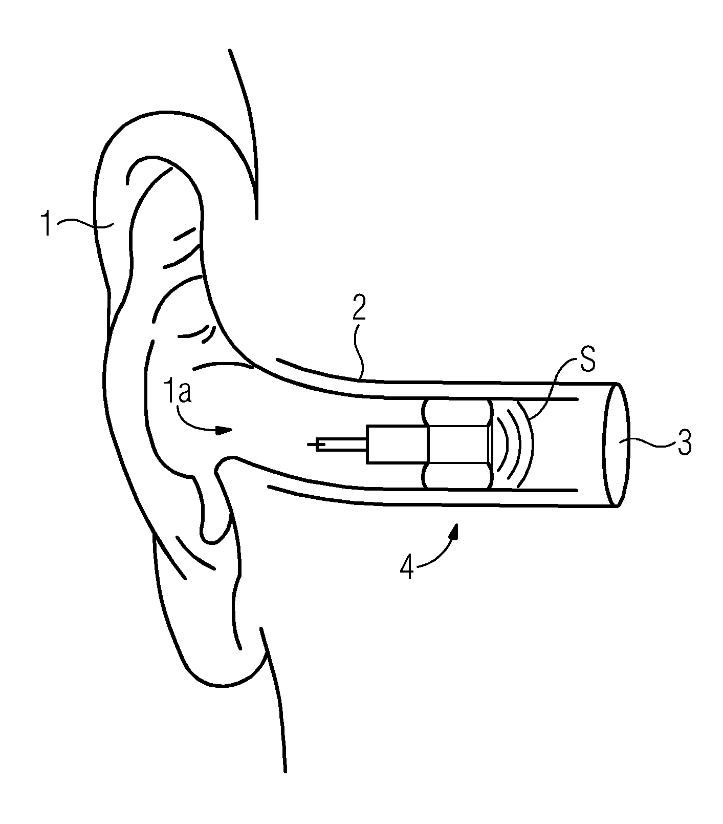
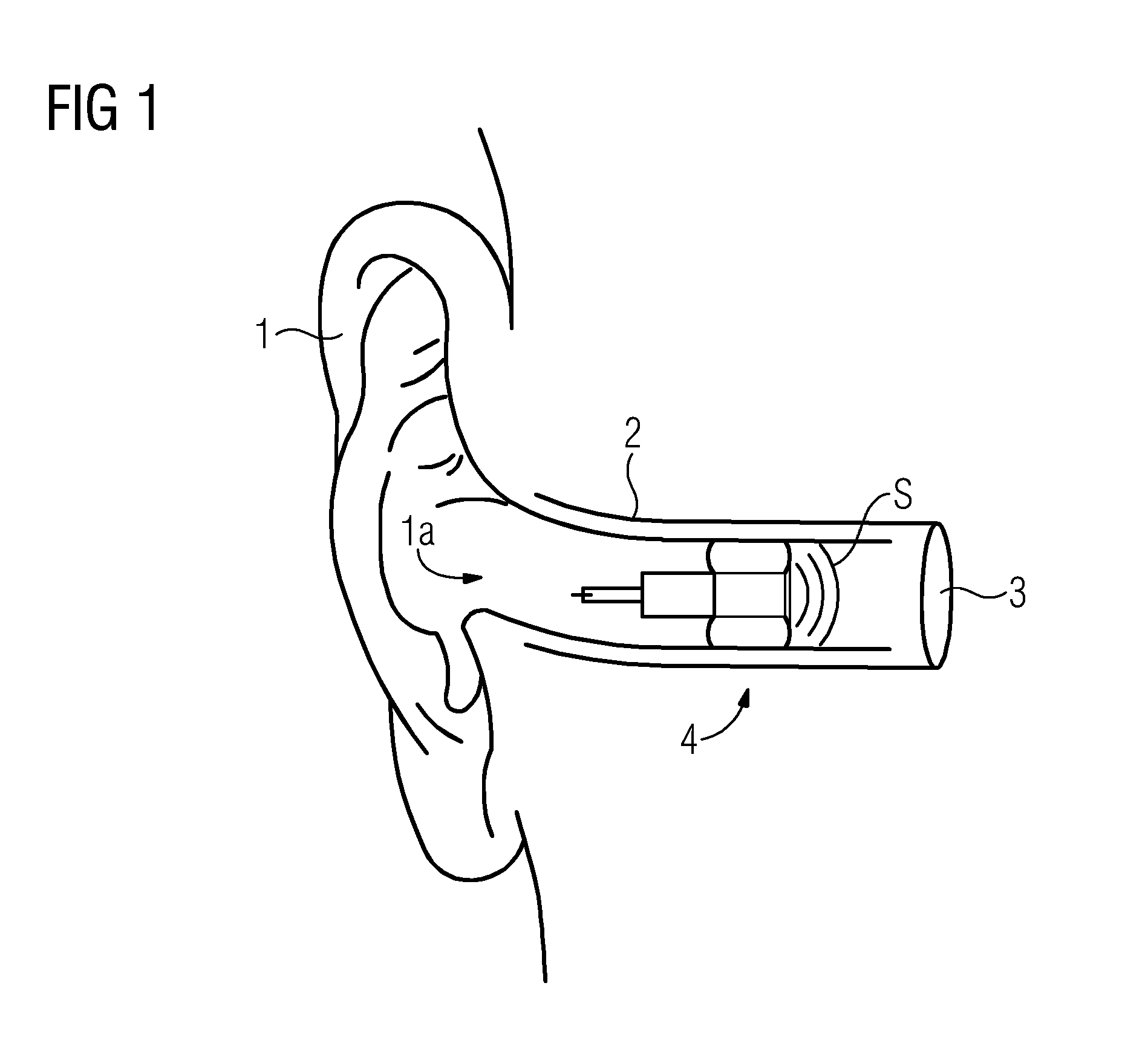
[0034]Referring now to the figures of the drawing in detail and first, particularly, to FIG. 1 thereof, there is seen a human ear 1 and an external auditory canal 2. The auditory canal is inwardly bounded by a tympanic membrane 3, also referred to as the eardrum. In unassisted hearing, pressure waves (sound waves are longitudinal waves with changes in pressure) are funneled at the concha 1a of the ear 1, they travel through the external auditory canal 2, also referred to as the ear canal or, simply canal, before they impinge on the tympanic membrane 3.

[0035]In assisted hearing, such as with hearing aids, the propagation of the sound waves through the auditory canal 2 is interrupted. The sound waves are instead picked up by a microphone or the like, the resulting signal is processed, typically by way of digital signal processing, and the processed signal is utilized to excite a loudspeaker, typically in the vicinity of or at the tympanic membrane 3. In the case of ear buds for music ...


PUM


Abstract

An inflatable ear piece is formed for insertion and placement in an external auditory canal. The ear piece has an inflatable balloon that may be selectively inflated and deflated. When the balloon is inflated, it expands and braces against the walls of the auditory canal. The ear piece has a receiver module with a sound generator and a connection to an exterior device. The sound waves generated in the receiver module are guided to the ear drum via a carrier which also holds the balloon. A pump and valve is provided for inflating, or selectively deflating, the balloon. The pump is connected by way of a micro tube that projects centrally inside the sound channel of the balloon carrier and its tip projects into a radial projection or a bridge across the sound channel. The receiver and balloon modules may be connected in any rotational orientation.

Description


Claims


Application Information

Patent Timeline
Owner SIVANTOS PTE LTD
Why Eureka
Try Eureka