Pipeline flow modeling method

a pipeline flow and flow modeling technology, applied in the field of mathematical modeling of pipelines, can solve the problems friction head loss, general increase of friction head loss, etc., and achieve the effect of facilitating a sequence of computations and accurate modeling

Active Publication Date: 2013-04-25
ENERGY SOLUTIONS INT
View PDF2 Cites 20 Cited by
  • Summary
  • Abstract
  • Description
  • Claims
  • Application Information

AI Technical Summary

Benefits of technology

This patent describes a method for predicting leaks in pipelines based on real-time monitoring of pressure changes. By using sensor data and mathematical models, the system can accurately track how different fluids behave when they move through a pipe. If there's no significant difference between what was expected and what actually happens, it means everything is going smoothly. But if there's any discrepancy, like a sudden drop in pressure, this could indicate a potential leak. In response, operators can quickly act to inspect the area and fix any issues before causing further damage or pollution. Overall, this technology helps ensure safe operation of pipelines and prevents accidents.

Problems solved by technology

The technical problem addressed in this patent text is how to effectively model the behavior of products in pipelines during different operational phases, particularly when there are changes in the way they affect the overall flow of the product. This includes identifying which parts of the pipeline are likely to experience slack flow and tight flow, and understanding what factors contribute to causing those transitions. The goal is to develop methods for accurate modeling these flow regimes without adding significant costs to the design and operation of the pipeline.

Method used


Image

  • Pipeline flow modeling method
  • Pipeline flow modeling method
  • Pipeline flow modeling method

Examples


Embodiment Construction

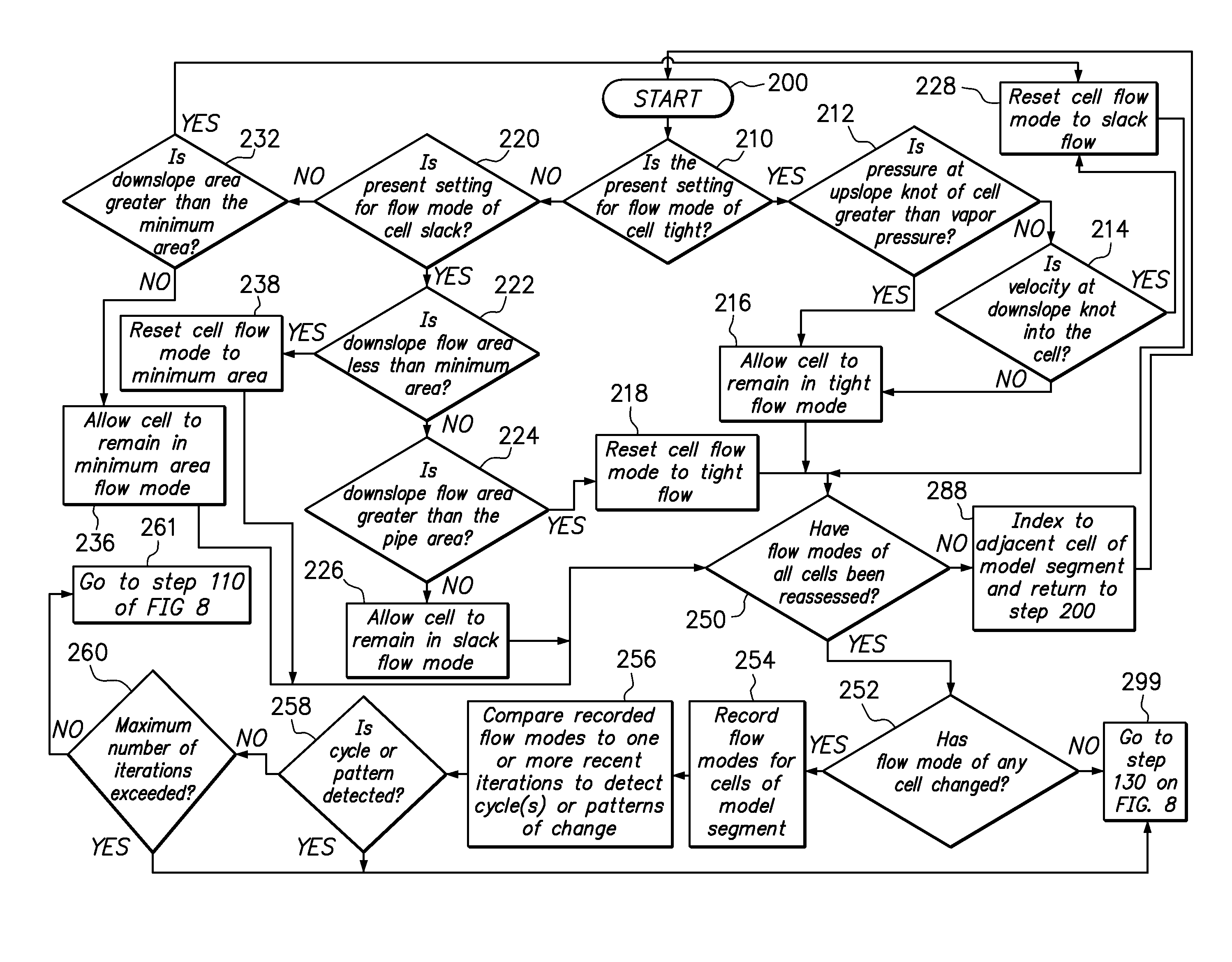
[0052]One embodiment of the method of the present invention provides a computer programmable method of modeling the flow, in a model segment of a pipeline, of a product having volatile components that provides stable computational hydraulic modeling of transient pipeline conditions including tight flow conditions; slack flow conditions; transitions between tight and slack flow conditions; shut-in (zero flow) conditions in slack regions; transitions to and from shut-in conditions in slack flow regions; transitions from forwards to backwards (reversed) flow in slack regions; transitions from backwards flow to forwards flow in slack regions; and drain down on both sides of a peak elevation traversed by the model segment. Embodiments of the method overcome the shortcomings of conventional models that fail to accurately model flow involving these and other transient conditions.

[0053]Embodiments of the method use three fixed state equations, relating the conservation of momentum, conserva...


PUM


Abstract

A method of modeling a segment of a pipeline transporting a product comprising defining within the segment a plurality of discrete cells, each disposed between knots, preparing a system of equations relating the conservations of mass, momentum and energy for each cell along with equations for the liquid phase flow area of cells with tight, slack and minimum area flow modes, providing data relating to the product and the location and elevation of the cells, sensing a plurality of conditions within known cells, solving the system of equations, initiating a re-stepping process by re-assessing the flow modes of each cell and re-setting flow modes for cells with unstable flow modes, and re-solving the system of equations using stable flow modes. An embodiment of the method includes excepting one or more cells from the re-stepping portion where a recurrent pattern of flow mode change is detected.

Description


Claims


Application Information

Patent Timeline
Owner ENERGY SOLUTIONS INT
Why Eureka
Try Eureka